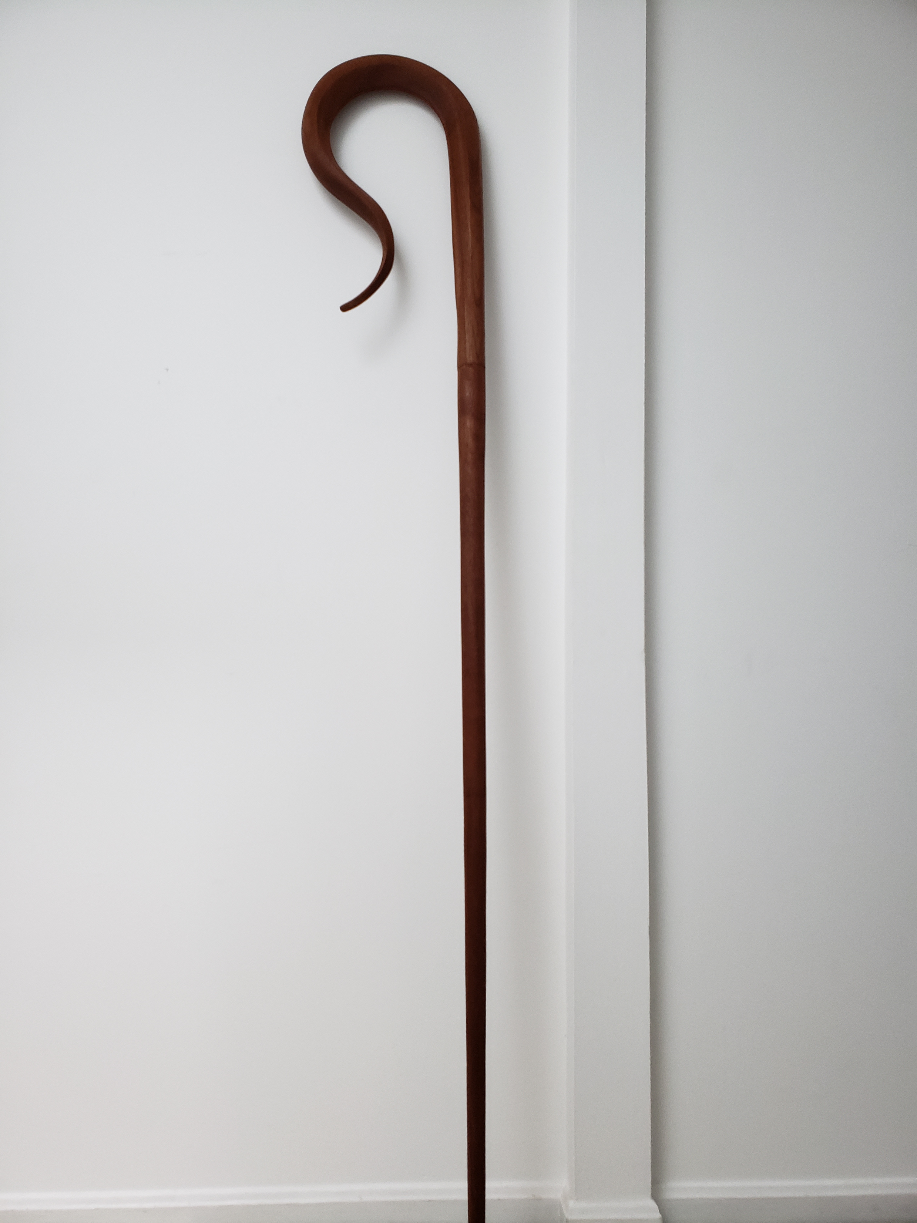
Bishop’s Crosier Rev 2
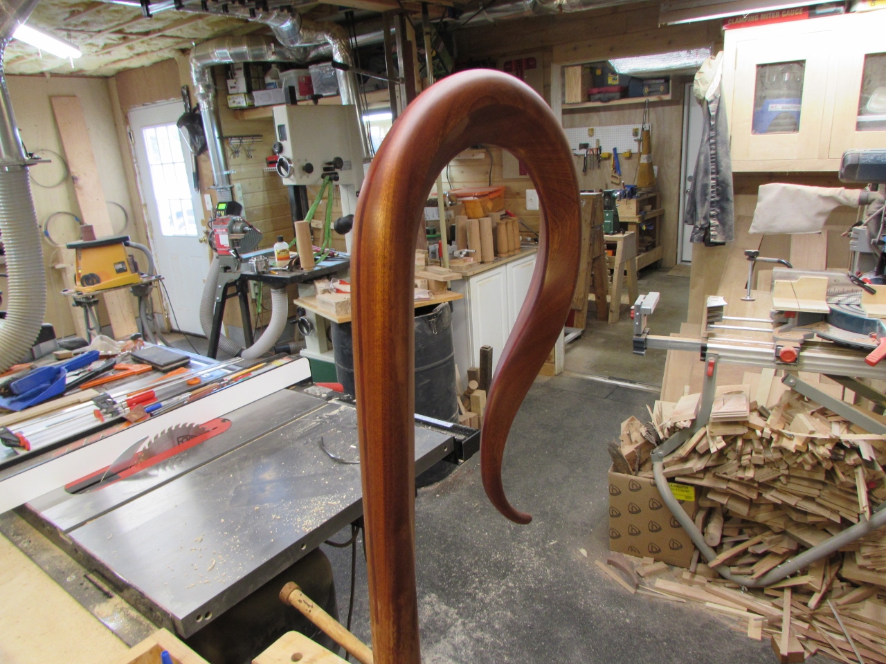
My friend Dave asked me to help him make another crosier. I wanted to revise the design of the previous crosier to incorporate some upgrades to the previous design. And of course, I learned a few more things on this one that I would like to incorporate into the next, but that will have to wait…
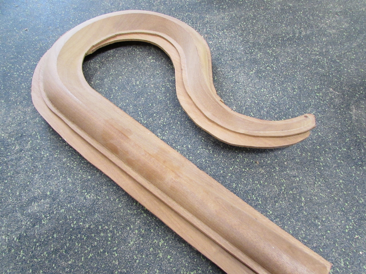
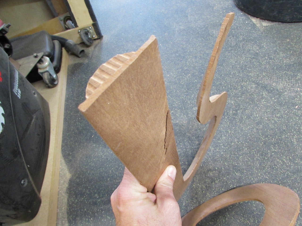
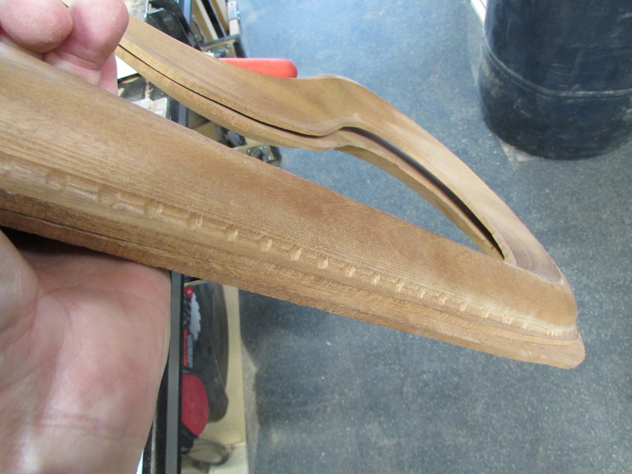
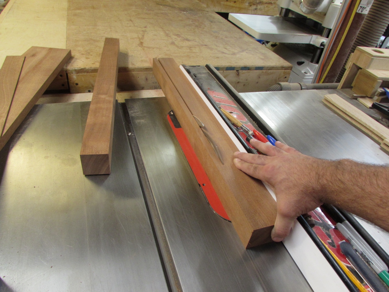
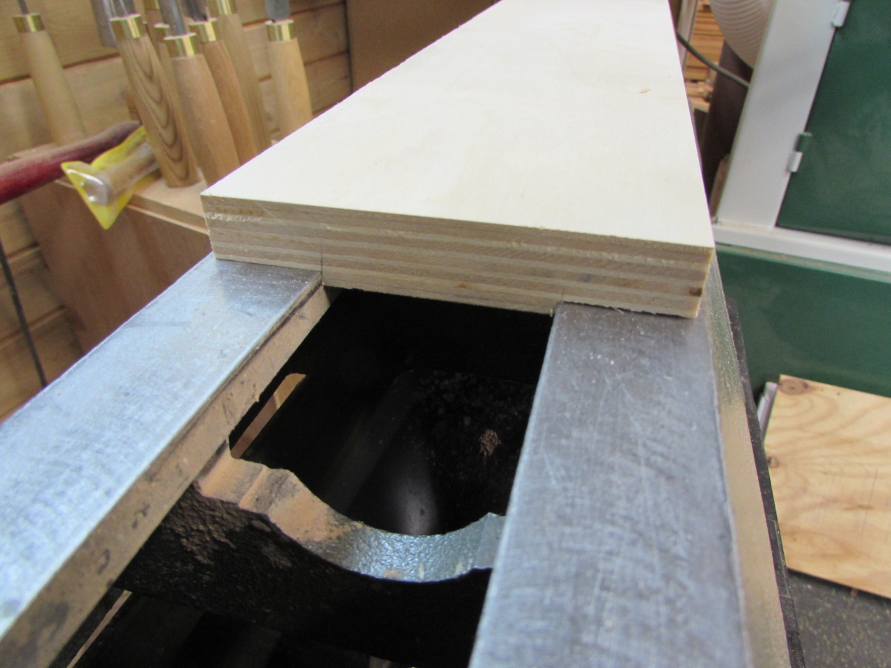
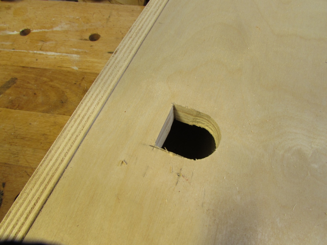
One of the problems that we ran into on the last one was with the head that Dave carved on his CNC. When he flipped the block of wood to carve the back half, something went wrong and the back half was shifted about 1/2″ off of the front. He attempted to re-saw that one so he could glue it back together in the right location, but I have never been able to do a perfect re-saw, on the band saw, and apparently Dave has the same problems.
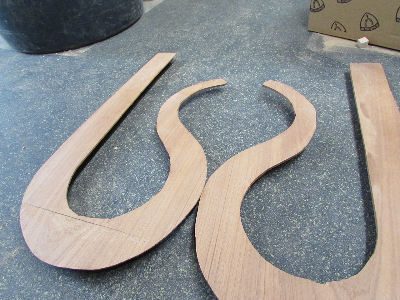
As you may be able to see from the pictures above and below, the blade sometimes wanders a bit and digs in, more to one side or the other, leaving a less than desirable glue surface.
I decided to take on the challenge of reusing the parts he carved, for this crosier. I have been thinking about how to fix it and I think I may have a way.
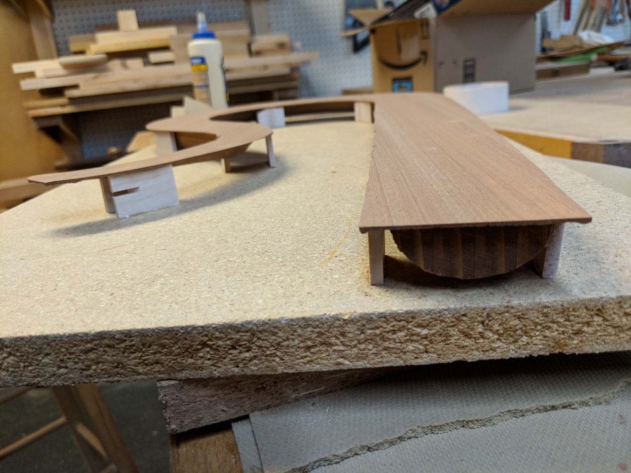
When Dave cut out his carved pieces, he left a rough flange behind. I decided to utilize this flange so I cut a bunch of 1″ x 3/16″ blocks, about 1-1/4″ long and used fast-curing CA glue to attach them
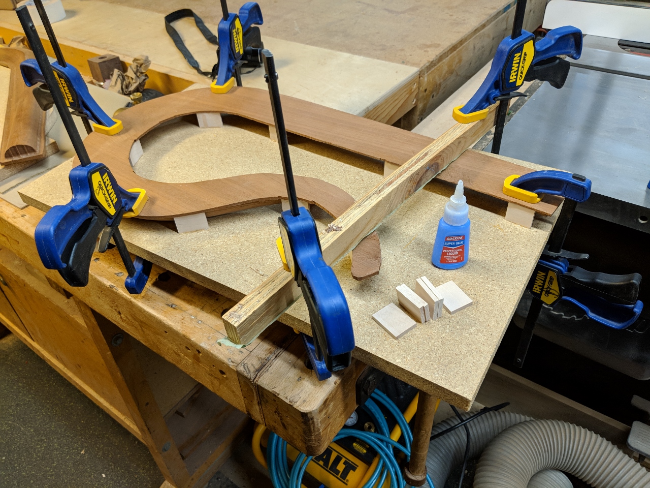
Next, I applied glue to the top of each block and flipped the whole thing face-down on a flat piece of particle board and held it in place for 30 seconds till the glue set. This takes out any twist that may have developed. It also gives me a flat reference plane to work with since the carve was not flat.
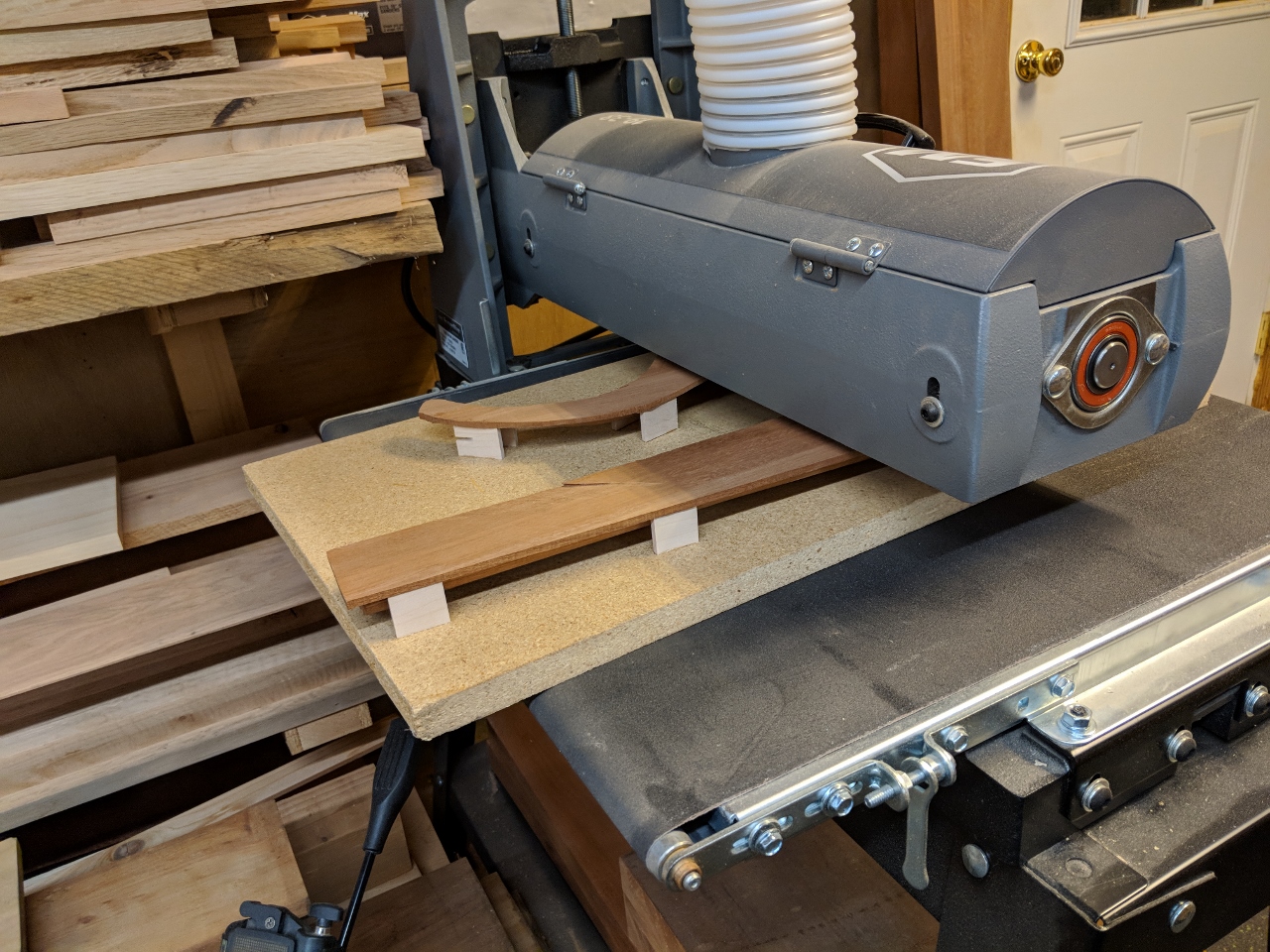
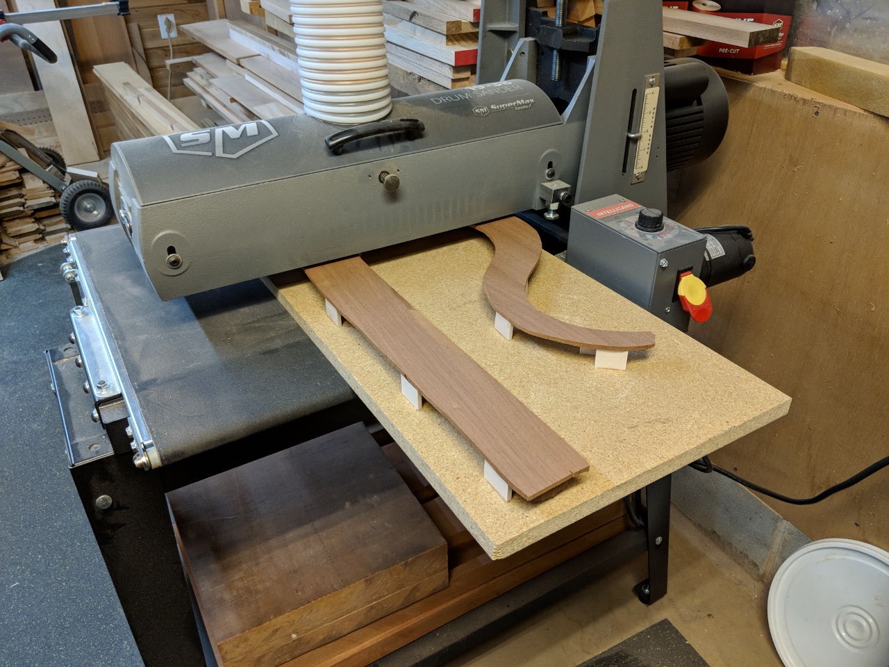
I ran the whole assembly through my drum sander several times, making very light passes.
When done, I was left with about a 1/32″ flange, but it was perfectly flat and smooth.
I repeated the process on the second half with similar success.
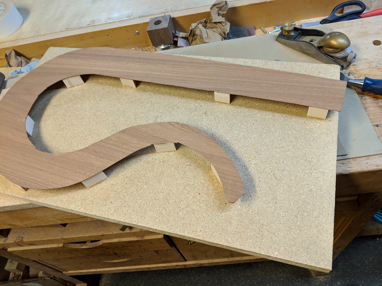
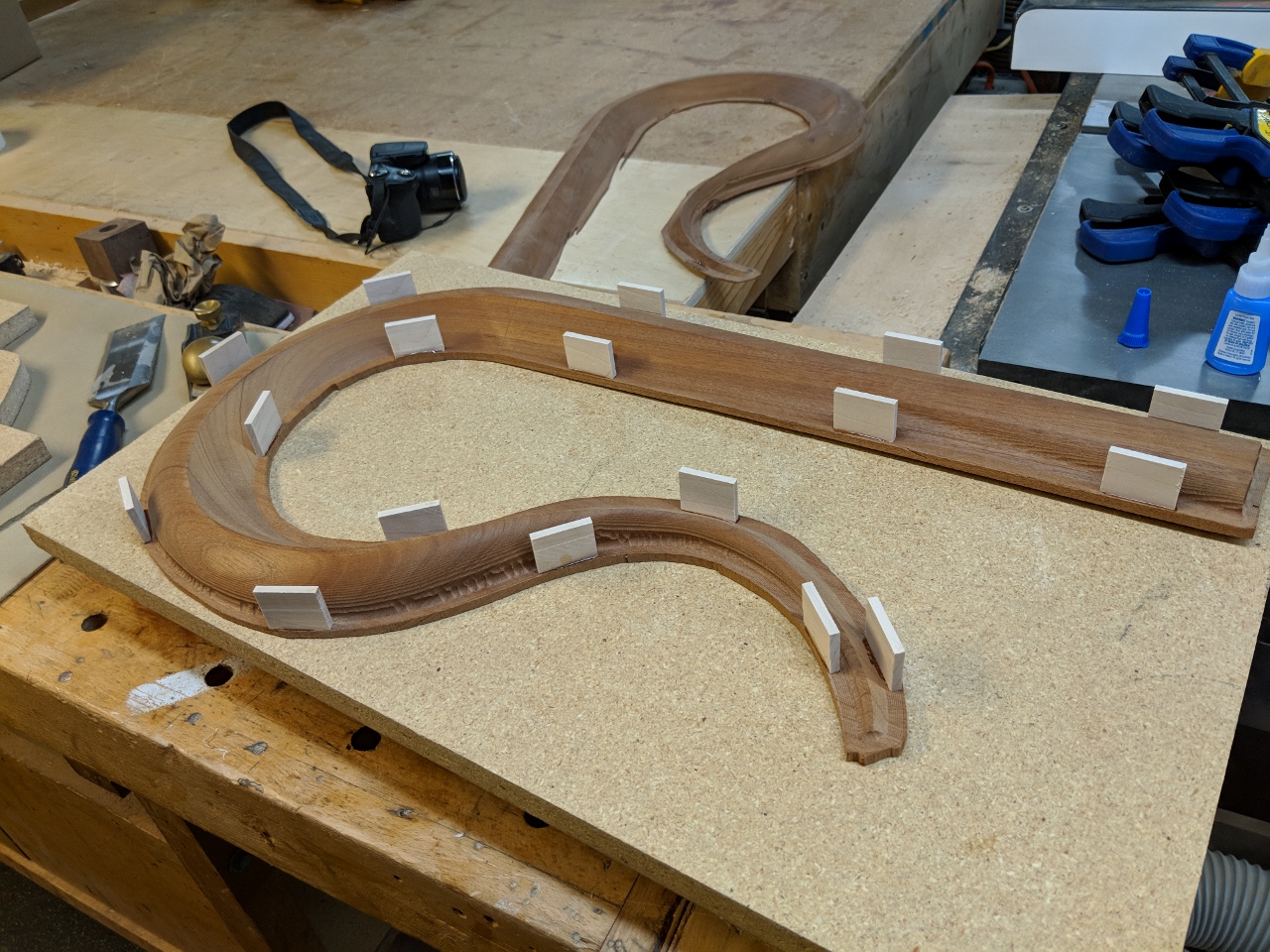
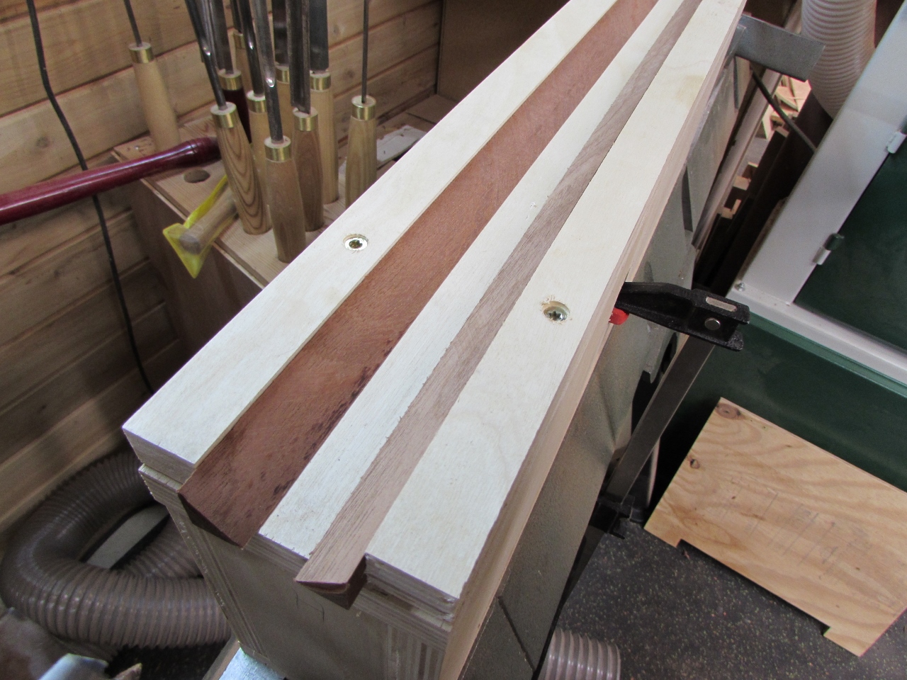
Dave’s original carve left about 1/4″ of material between the two carves. When trimmed away, the body would have been round. But since I had to sand away that extra thickness, I needed to add it back in. This was an excellent opportunity to strengthen the re-curve, which broke off of the last one. Instead of cutting more sapele to try to hide the join, I decided to highlight it with red-heart instead.
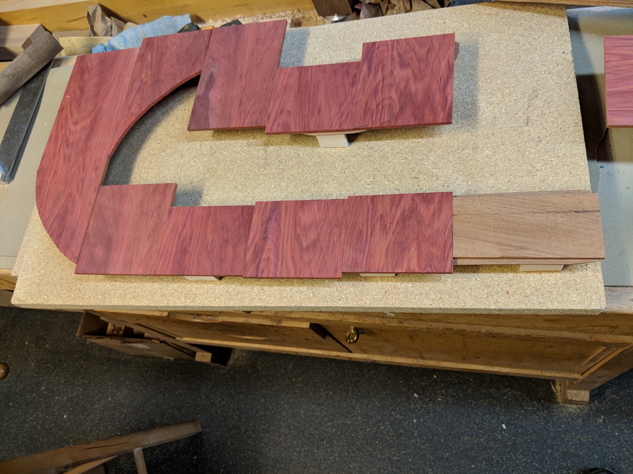
I re-sawed a small piece of red-heart and sanded it down to 3/16″ thick, then cut and glued several pieces with their grain running perpendicular to the sapele. I did use one small piece of sapele at the bottom so that it would look like continuous grain at the joint.
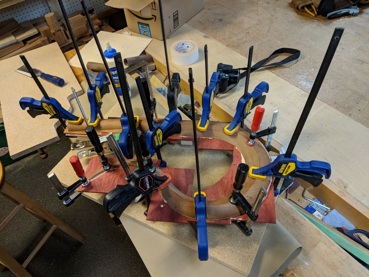
I used regular wood glue and a bunch of clamps to hold it all together for a couple of hours till the glue was set enough to work with.
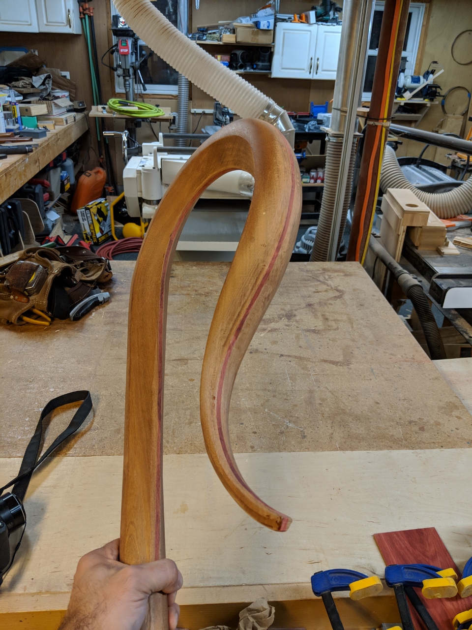
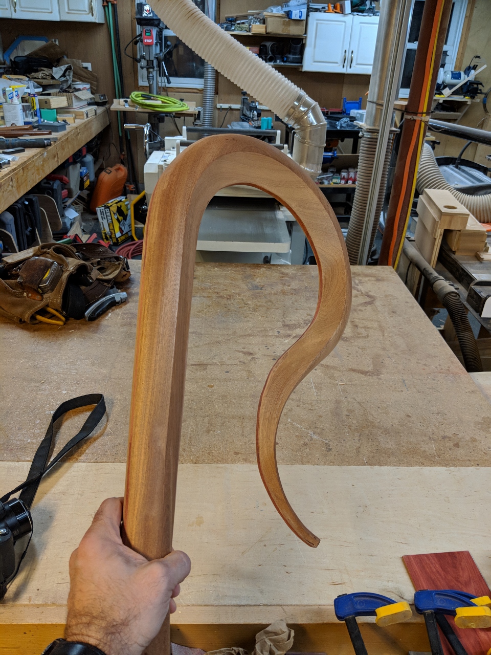
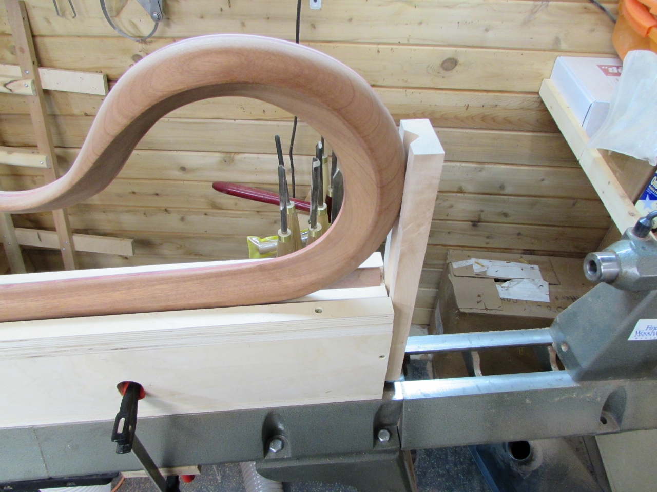
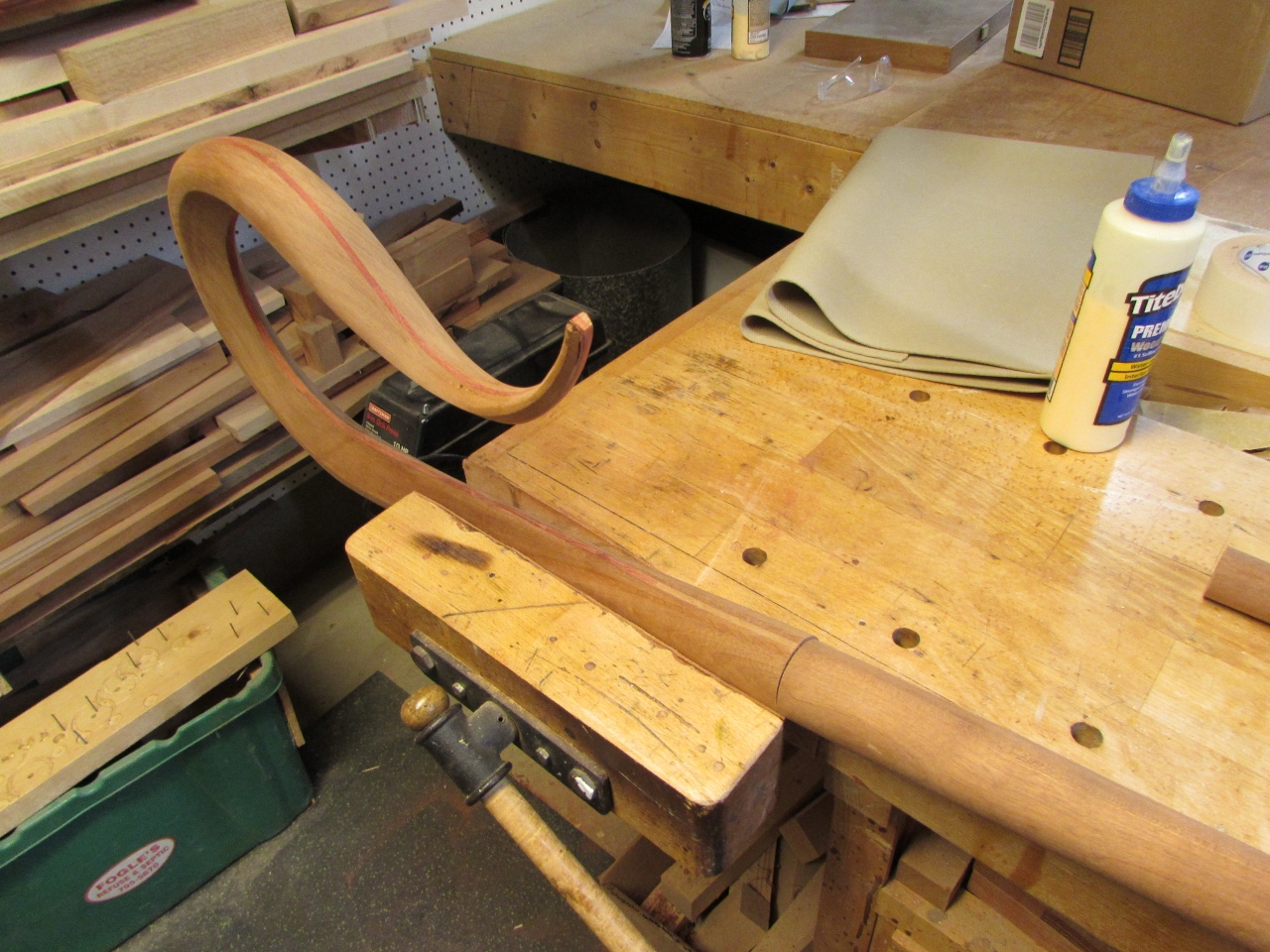
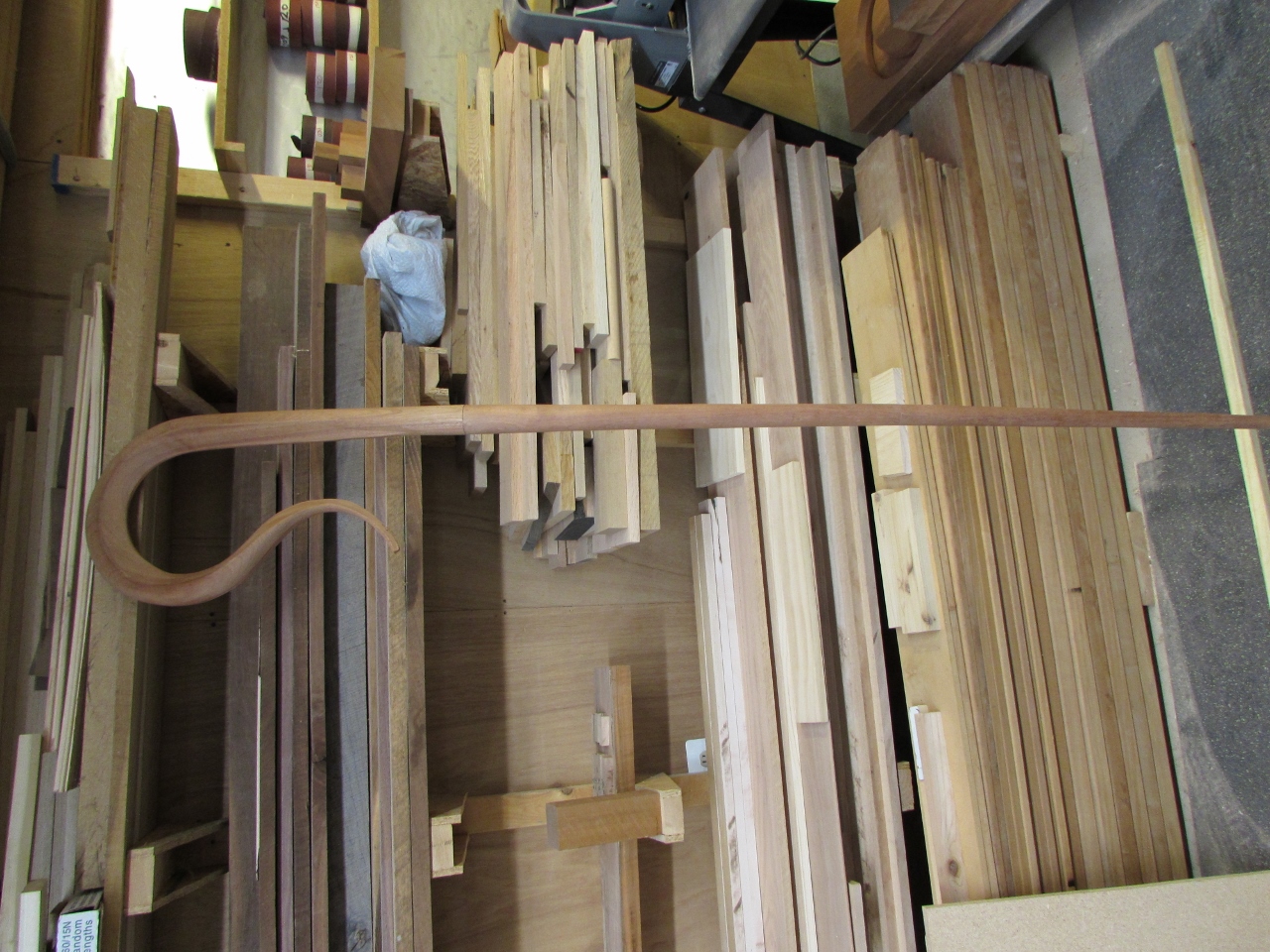
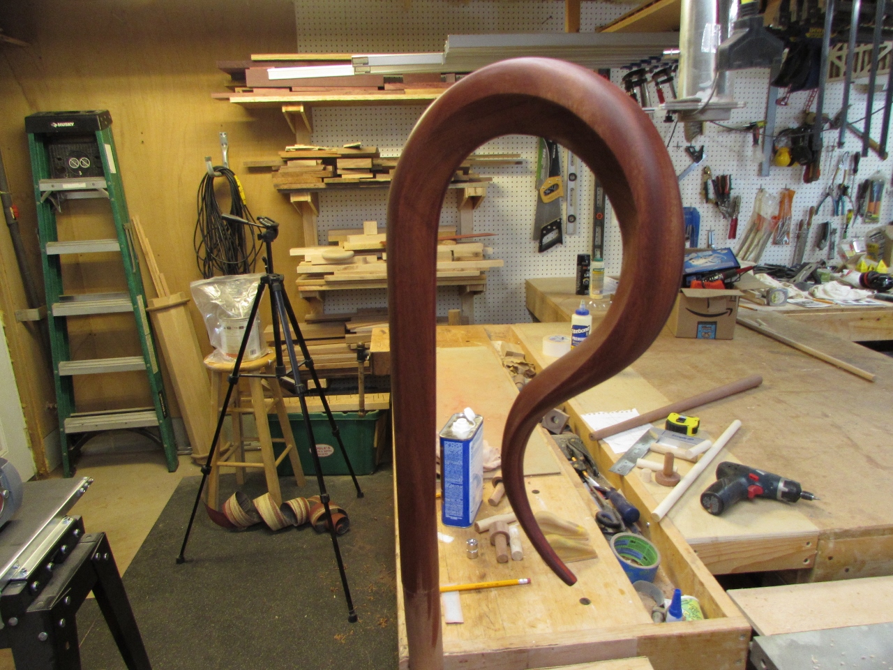
Then I cut away the excess on the band saw and used a rasp to roughly clean up the joint. The re-curve is surprisingly strong.
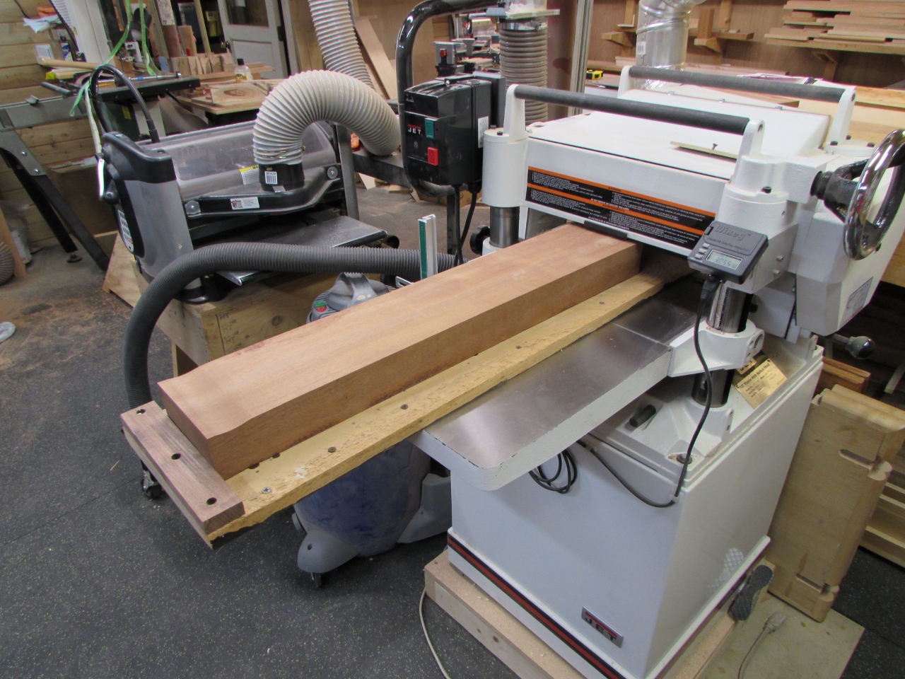
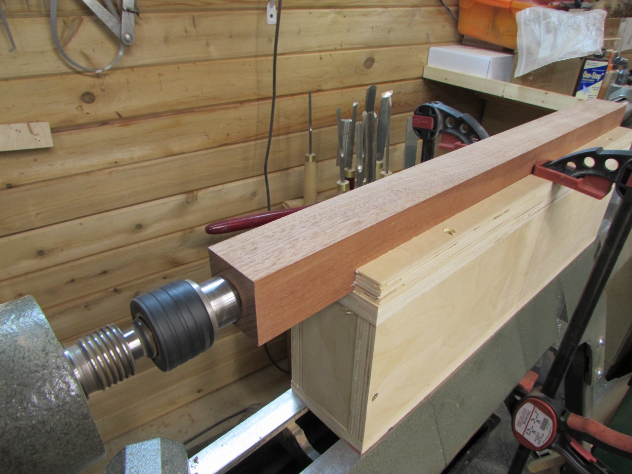
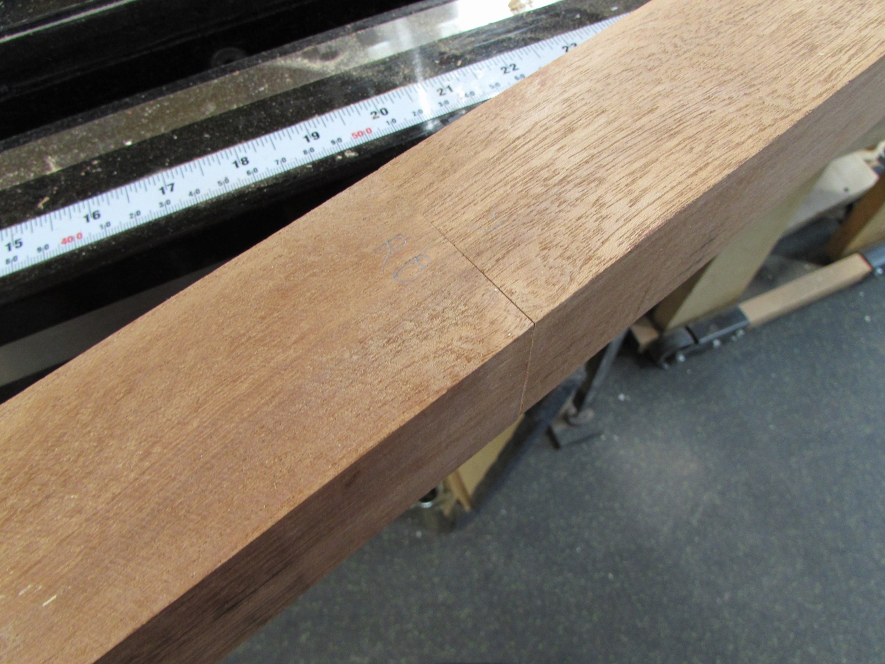
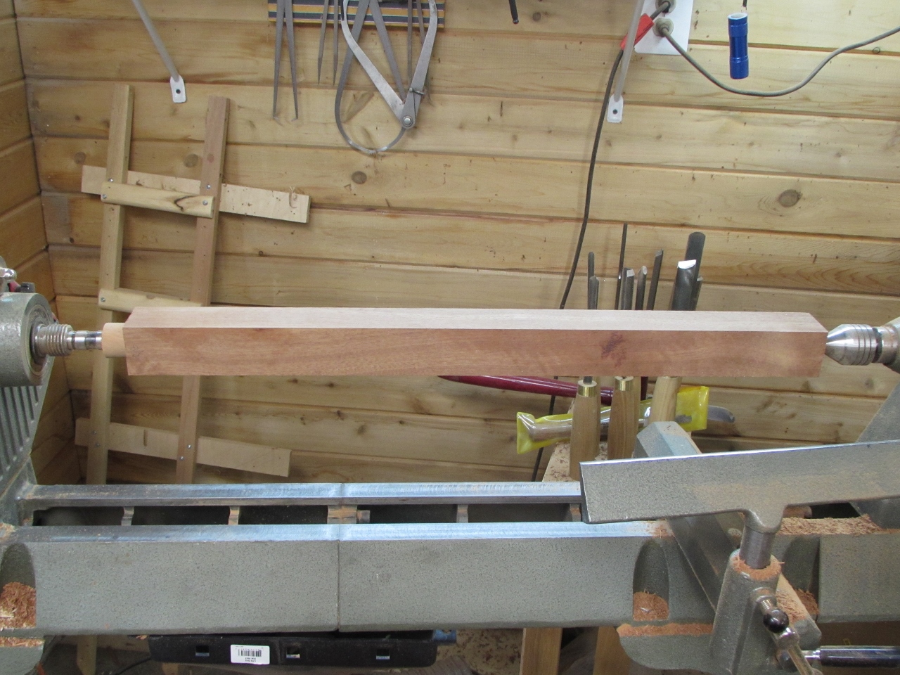
With the head mostly complete, it was time to move on to the leg. I have an off-cut from the wood Dave carved the head from, so I flattened one side, on my planer sled, then planed the other side down until the board was exactly 2″ thick.
Then I cut two 2″ wide pieces from that board. These will be the two sections of the leg.
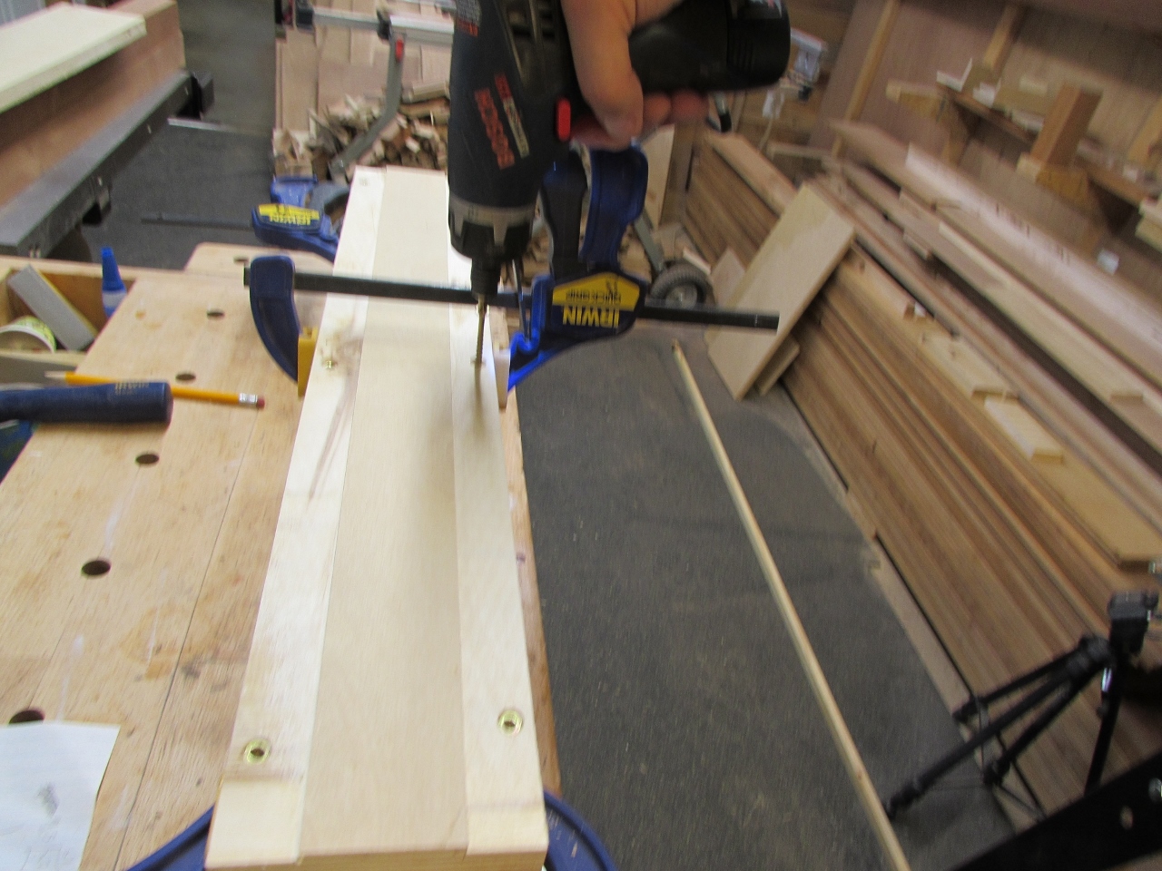
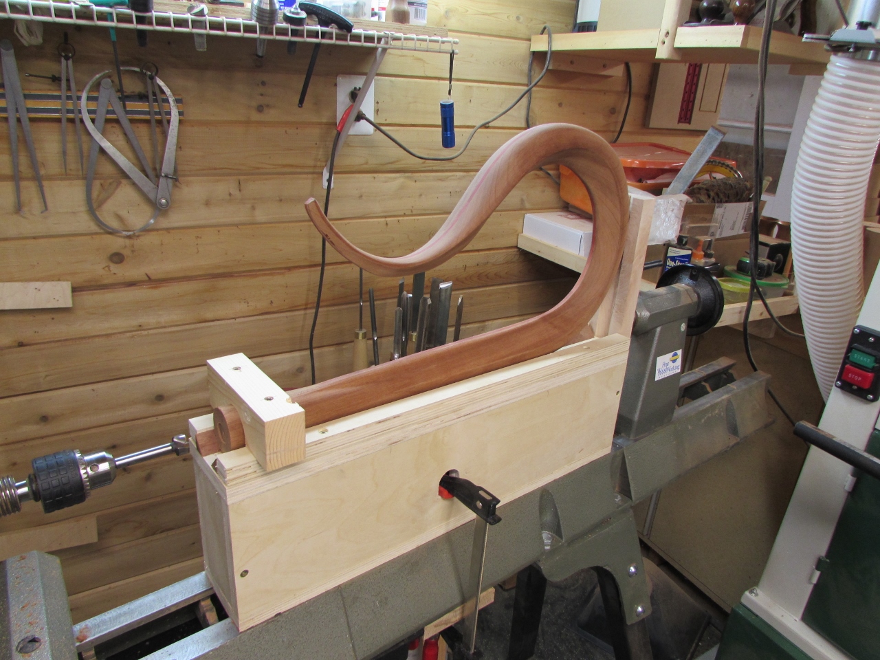
Before turning the legs, I need to switch gears and figure out a way to drill the connection holes, in each of these pieces, so that they are perfectly perpendicular to the end allowing everything will connect seamlessly. On the last one, I made a small drill jig and tried using a hand drill and a 3/4″ bit. It did not go well. The bit was too aggressive and ate up my jig enough to create an elongated hole.
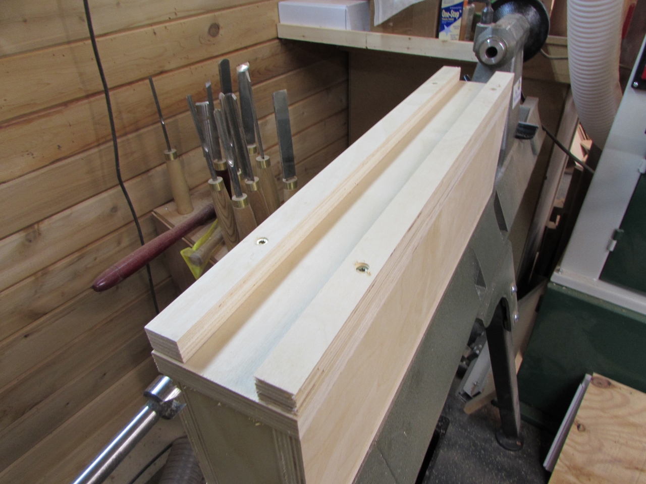
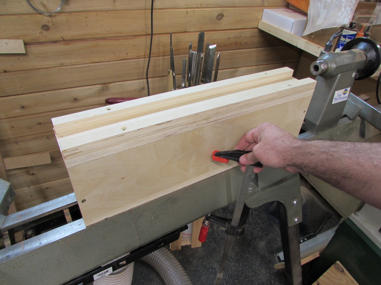
After a lot of thought, I decided that I need to build a jig for my lathe that would hold everything in line with the centers. I observed that my lathe bed was machined so that the front and back of it ran perfectly parallel, in line with the centers. I decided to utilize this by notching both sides of a piece of plywood so that the part left-over was a press-fit into that channel.
This would be the base of my jig. I measured the height from the bed to the center and subtracted 1″ (half the thickness of my blanks).

Using that dimension (7″) I built a box as square and accurately as I could, out of 3/4″ plywood.
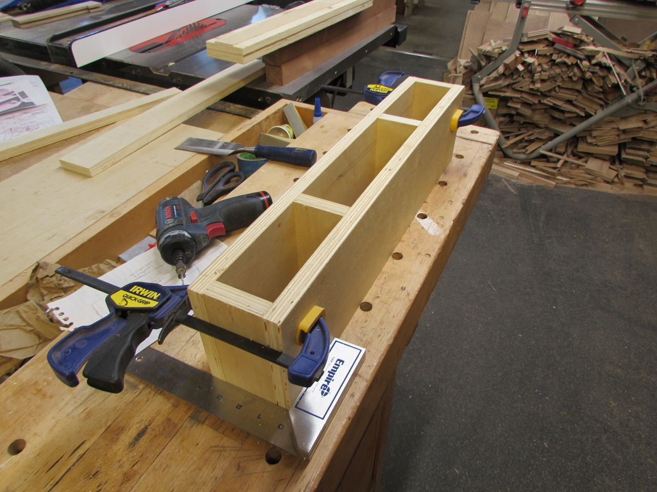
Everything was screwed together (not glued, in case it needed to change) with 2″ screws.
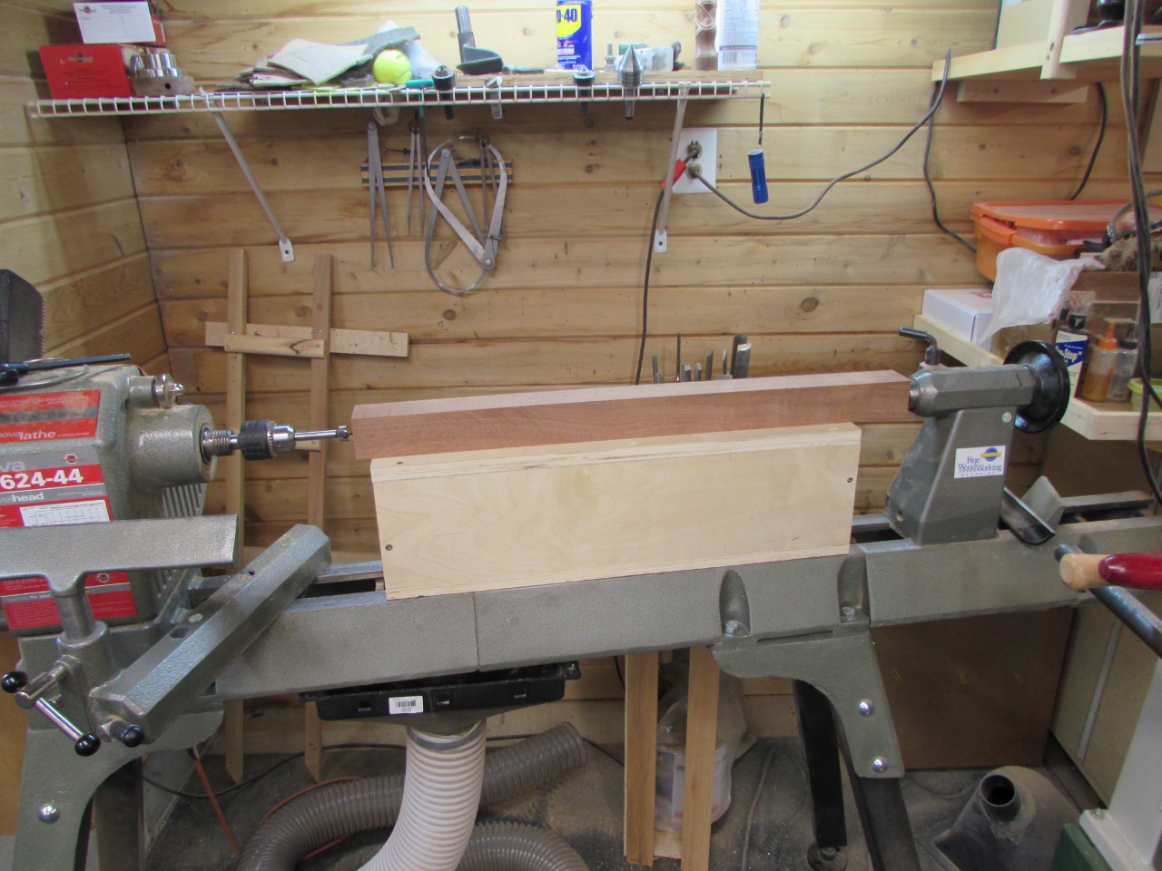
When installed on the rails, my blanks set exactly centered, vertically.
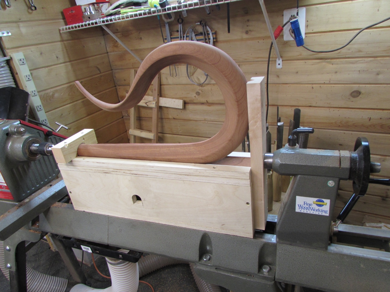
Then I cut rails for each side and screwed them down. Here I made a small mistake. I assumed that everything was perfect and screwed the strips in, lined up with the sides of the jig. I should have held the blank between two centers and then butted the side strips against the blank to fix a location exactly parallel to the centers. My mistake caused me to be about 1/2 a degree off, which I found out later and had to fix.
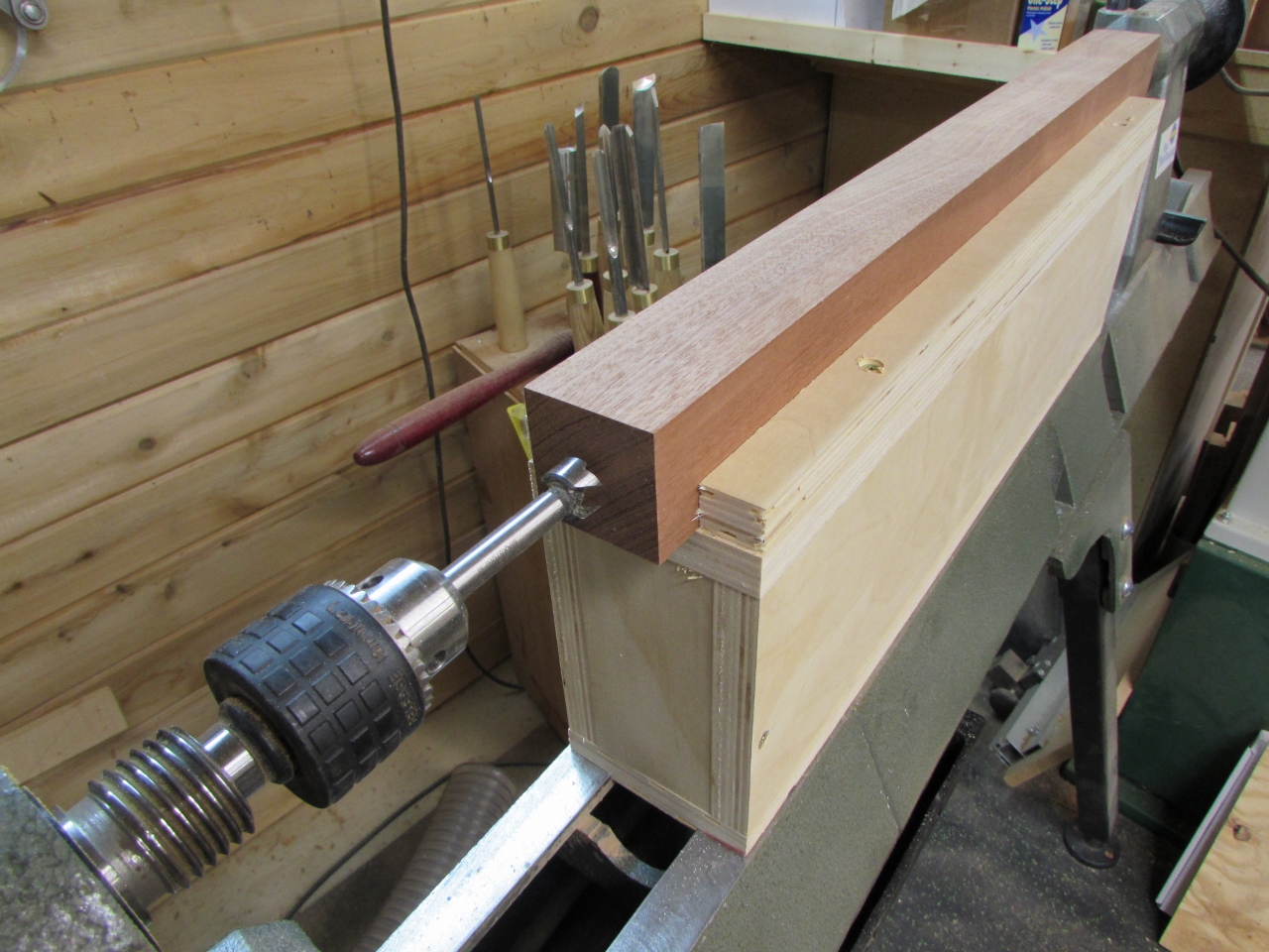
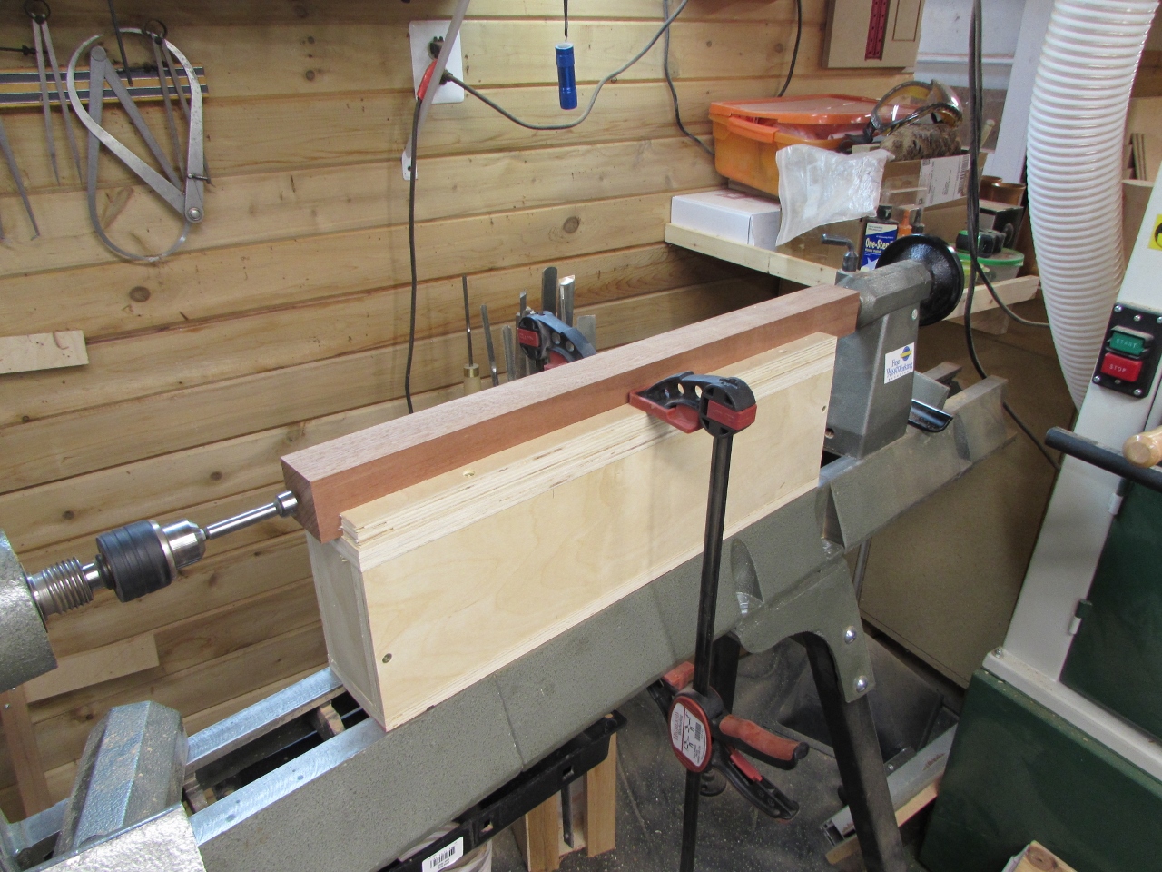
I added a couple of clamps to hold the box in place, then I was ready to drill.
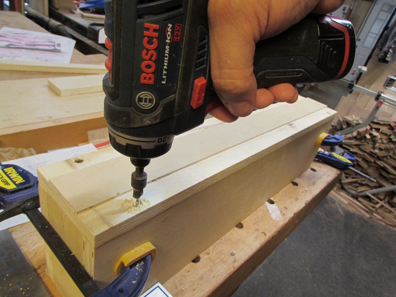
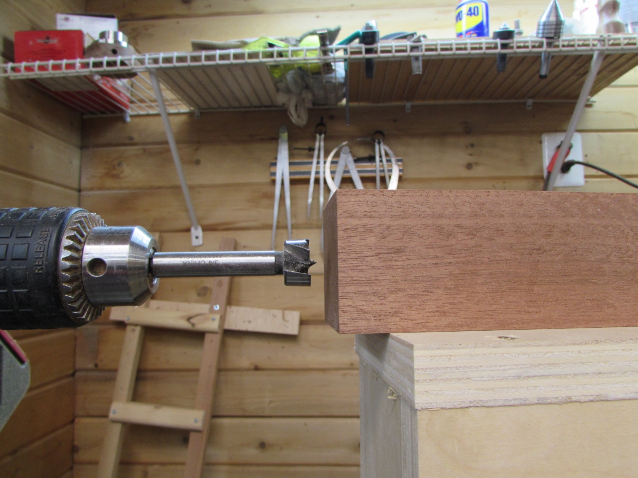
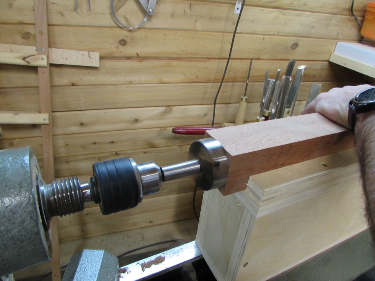
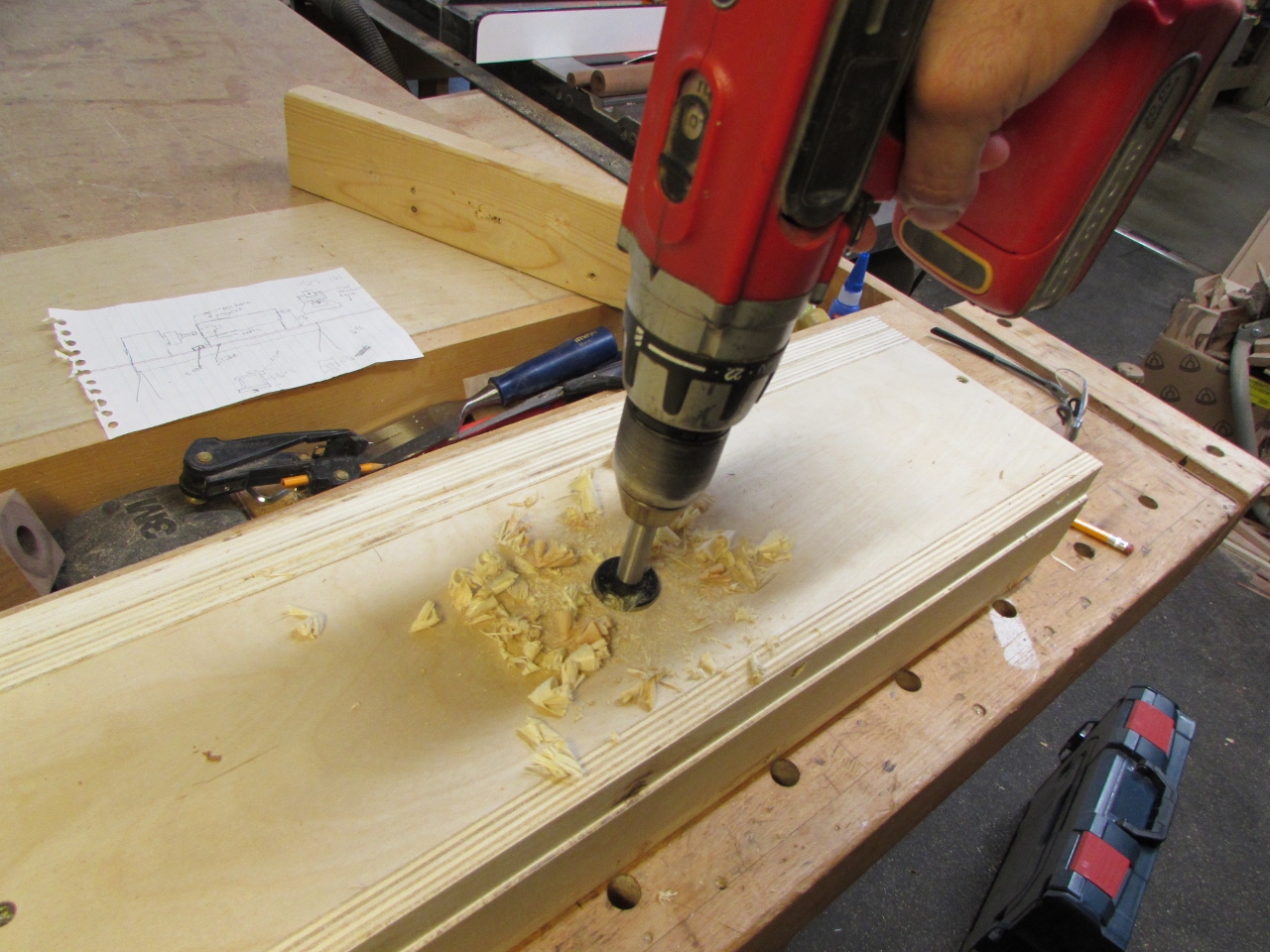
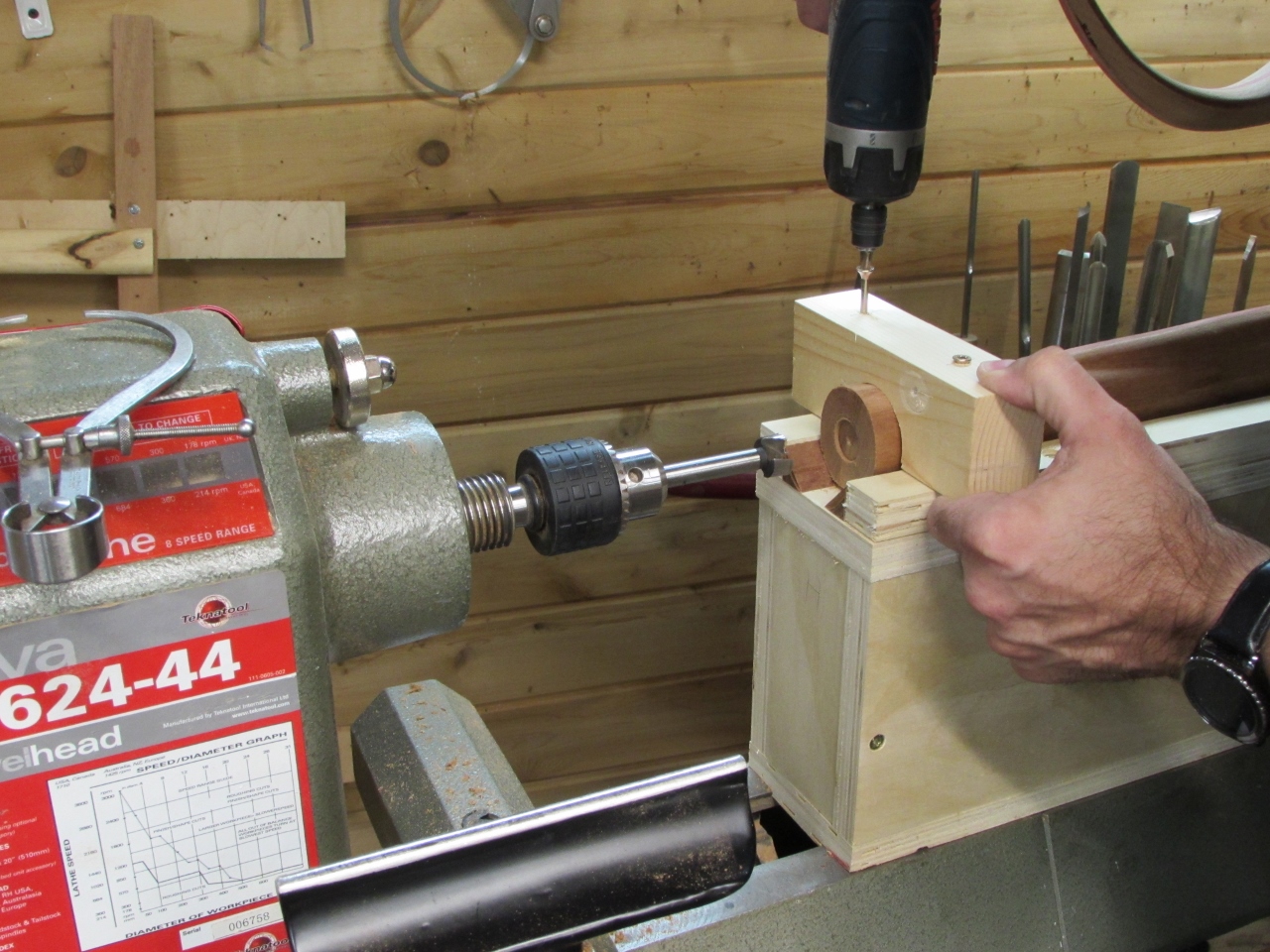
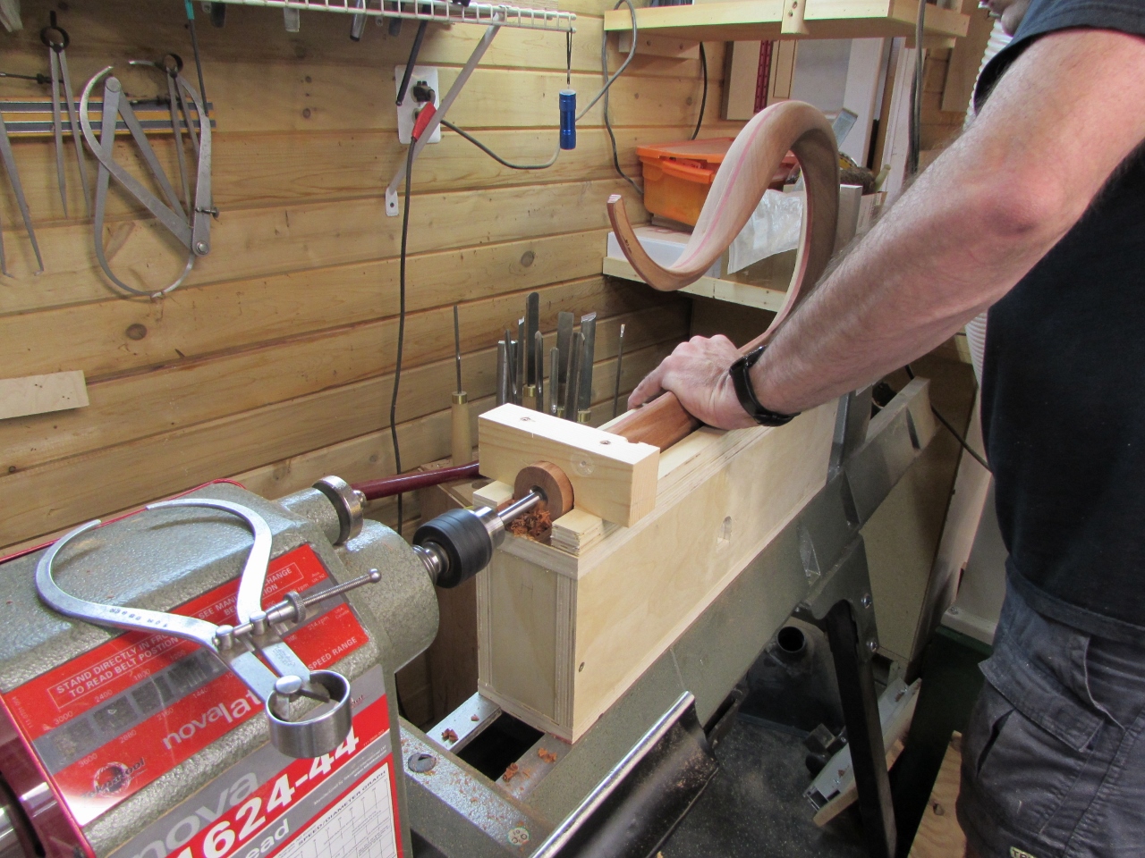
The forstener bit is the most accurate yet least aggressive bit that I have. I usually use a drill press, but the lathe is better suited for this operation. I can’t easily push the blank onto the bit by hand, but I can drive it forward with my tail stock.
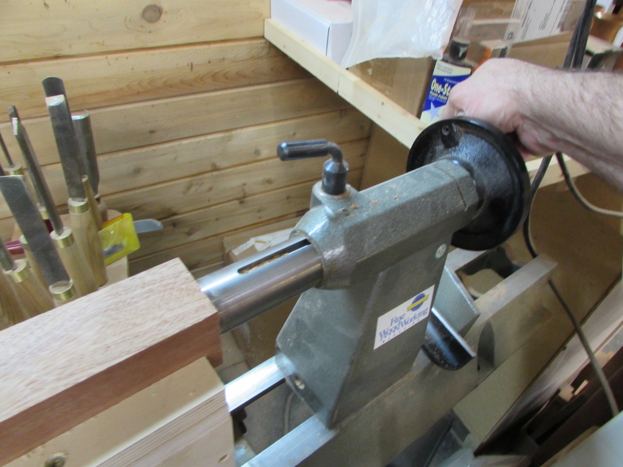
This worked way better than I expected. I had to manually back the blank off the empty the shavings out of the hole, every 1/4″ or so of drilling, but it worked well.
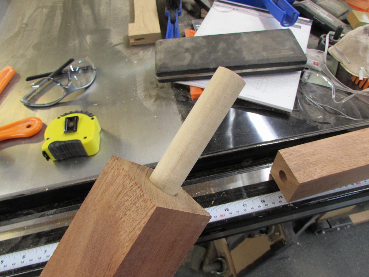
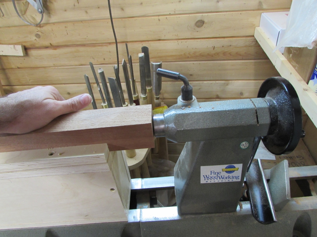
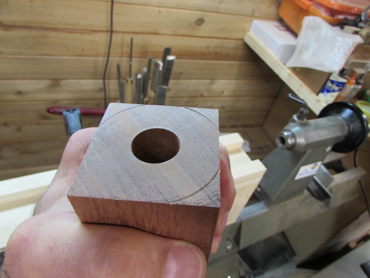
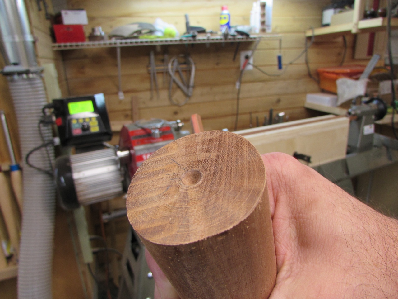
After I got my holes drilled, I inserted a 3/4″ wood dowel to check the alignment.
It looked good in one direction, but after rotating one of the blanks 180 degrees, the 1/2 degree error in the jig became evident.

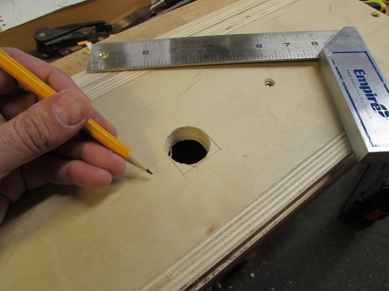
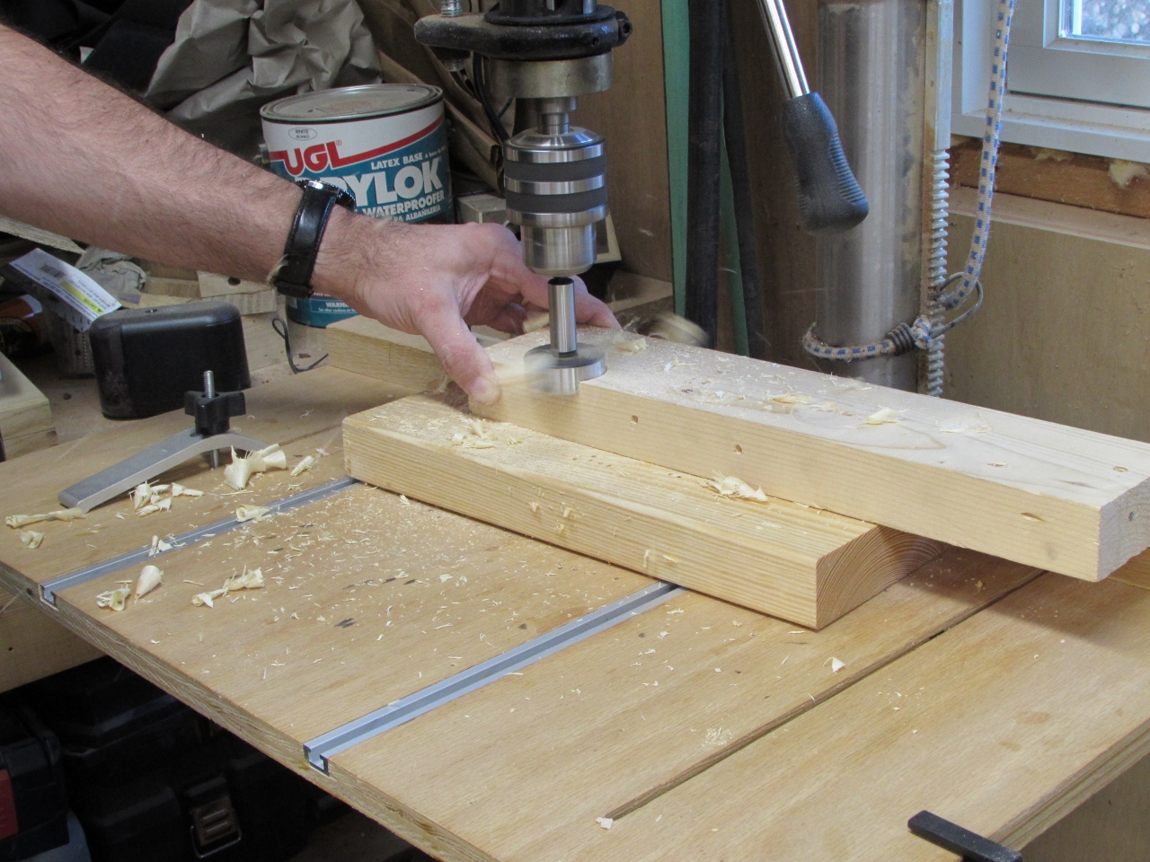
While everything was still set up, I tried a quick fix. I got the biggest forstener bit that I have (2-1/8″) and tried drilling the end face to create a flat end perpendicular to the hole.
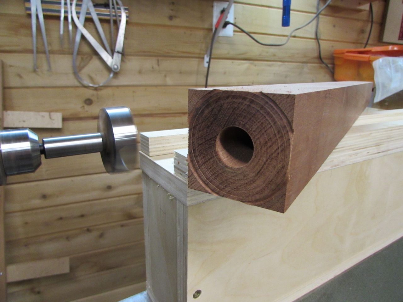
I could definitely see that it was off after hitting the face.
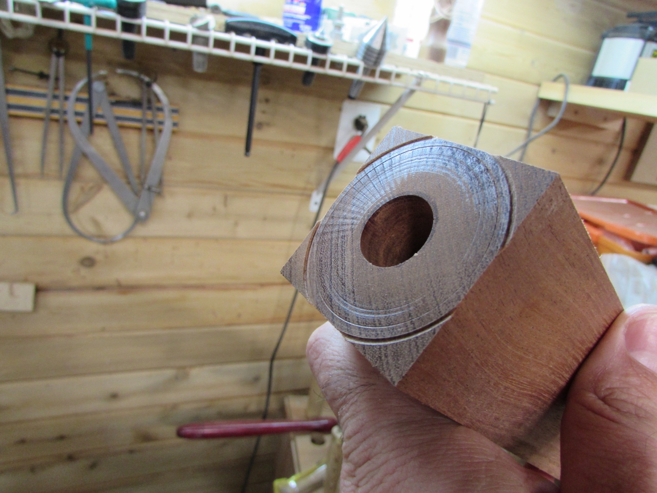
It would have been smarter to face the board with the large bit first so I had a center point to follow. It worked fairly well, but I had a bit of chatter. Good to know for the next one…
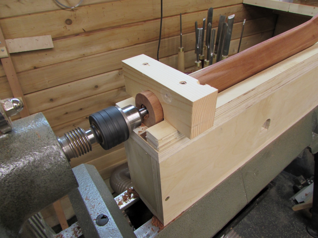
I need to make some bushings for the ends of the legs, so I grabbed a left-over piece of hard maple and started turning it down.
Then I hit a crack and destroyed the blank…
But it was a good thing. I realized that I needed to work from a smaller blank so I could reuse the center points punched into each end, by the lathe. If I cut the bushings from the middle, as I was doing, I would need to add new center points that would never have been as accurate.
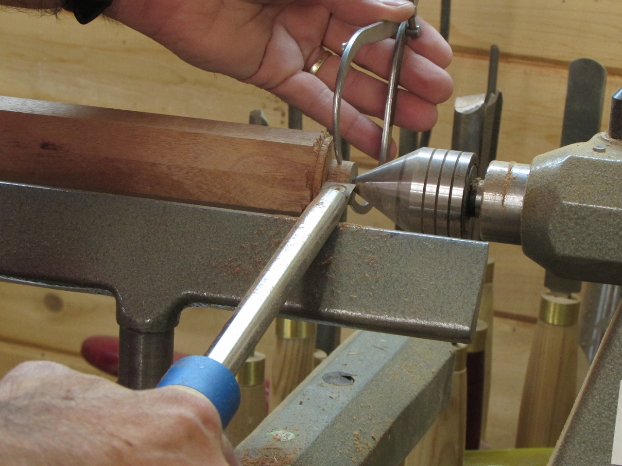
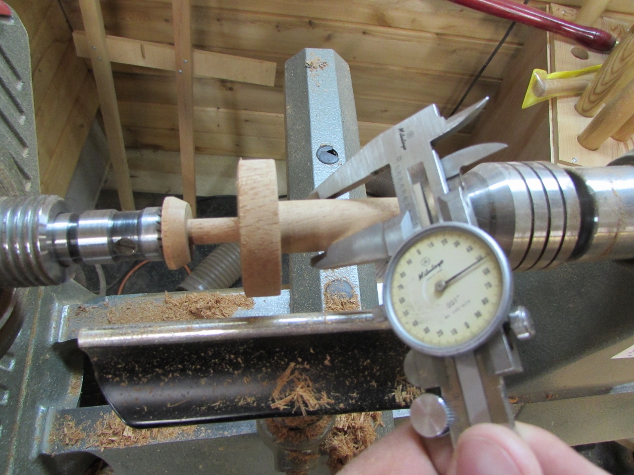
I am making two bushings from one 5″ blank. The larger diameters, on the ends, will be the final diameters of each end of the tapered leg sections.
I took great care to make the center exactly 3/4″ by cutting it down as closely as I could and sanding down to the final dimension.
I chamfered the ends and parted the two pieces.

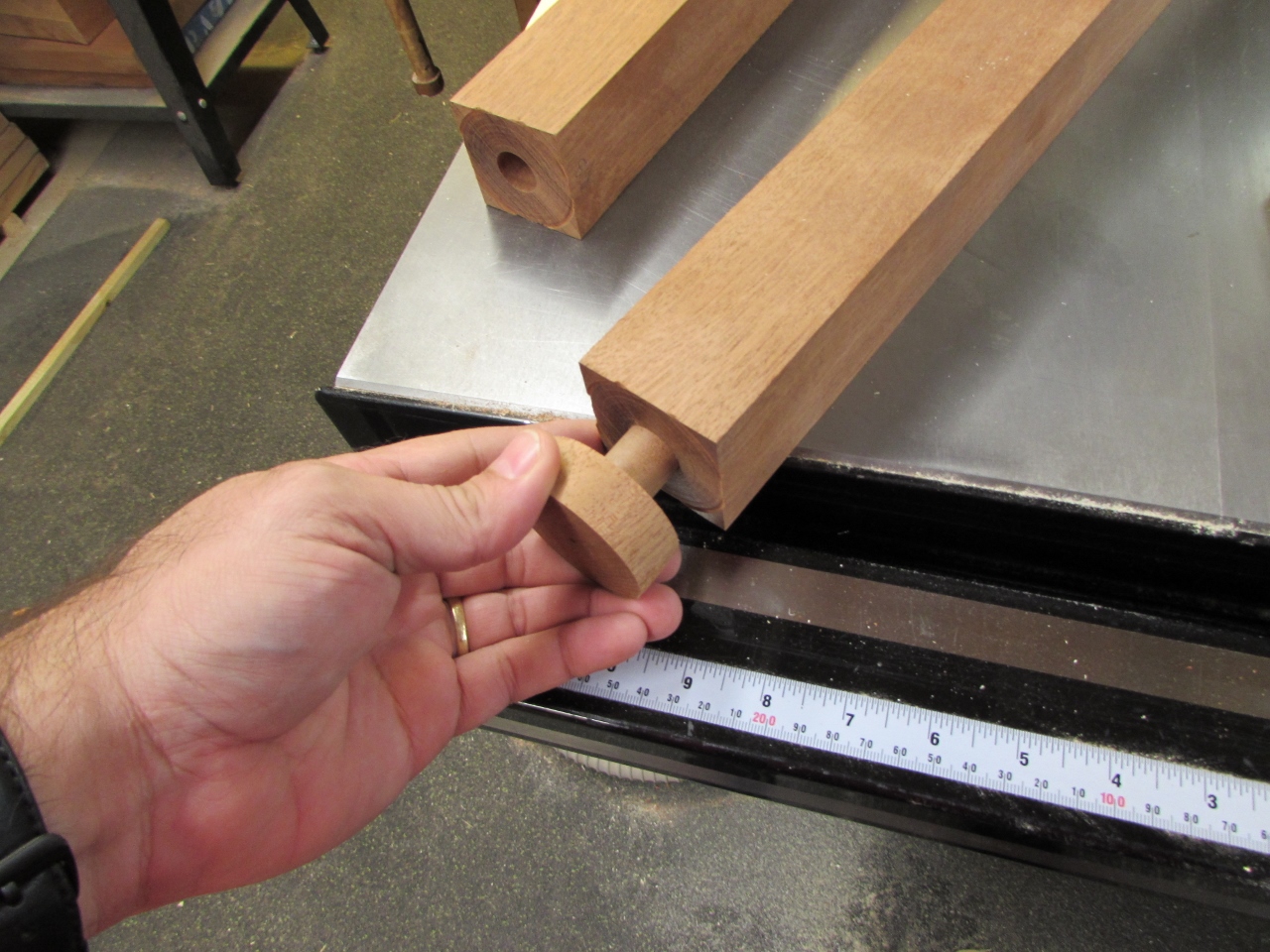
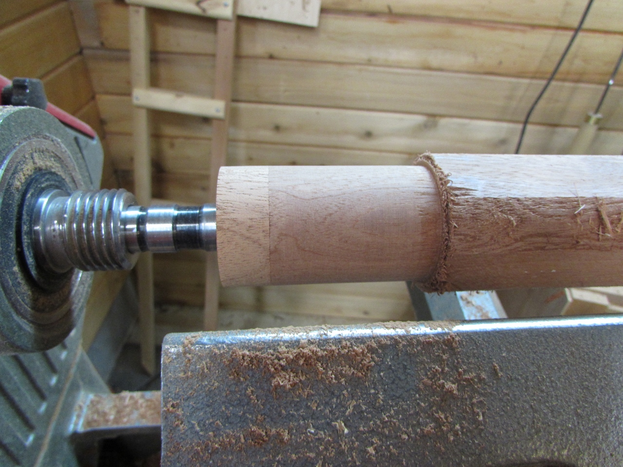
By carefully sizing the center portion, I have a near perfect fit into the leg section. It even creates a small vacuum and a popping noise when removed. This is critical to keep the bushing dead center in the leg.
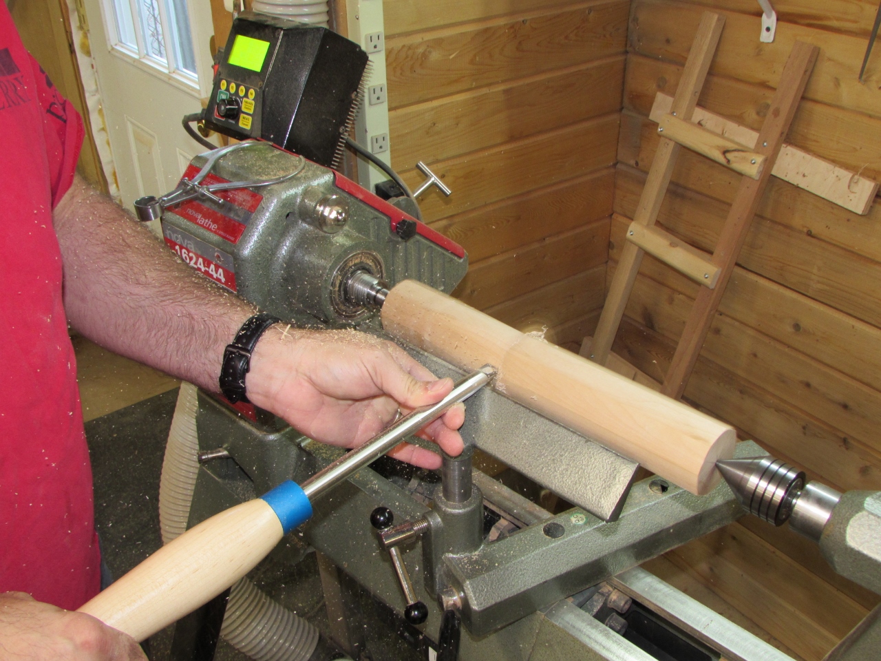
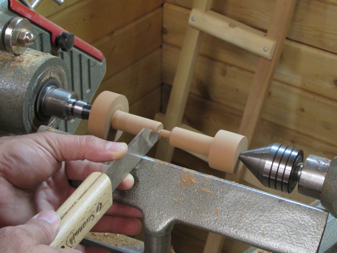
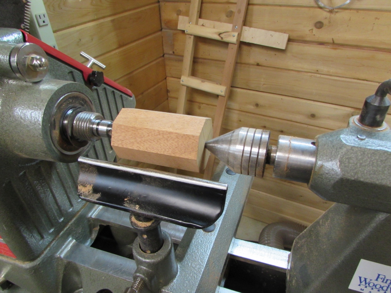
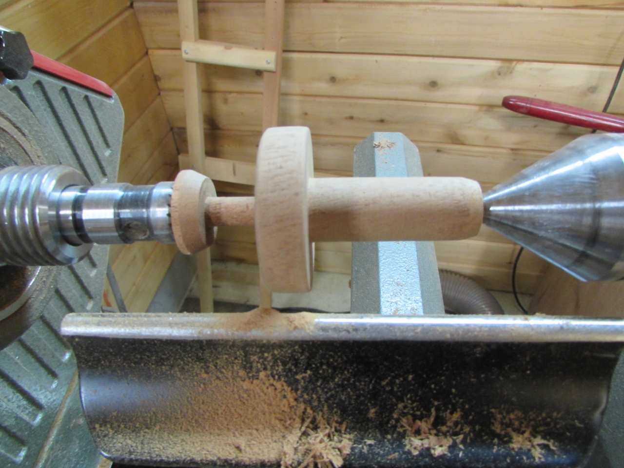
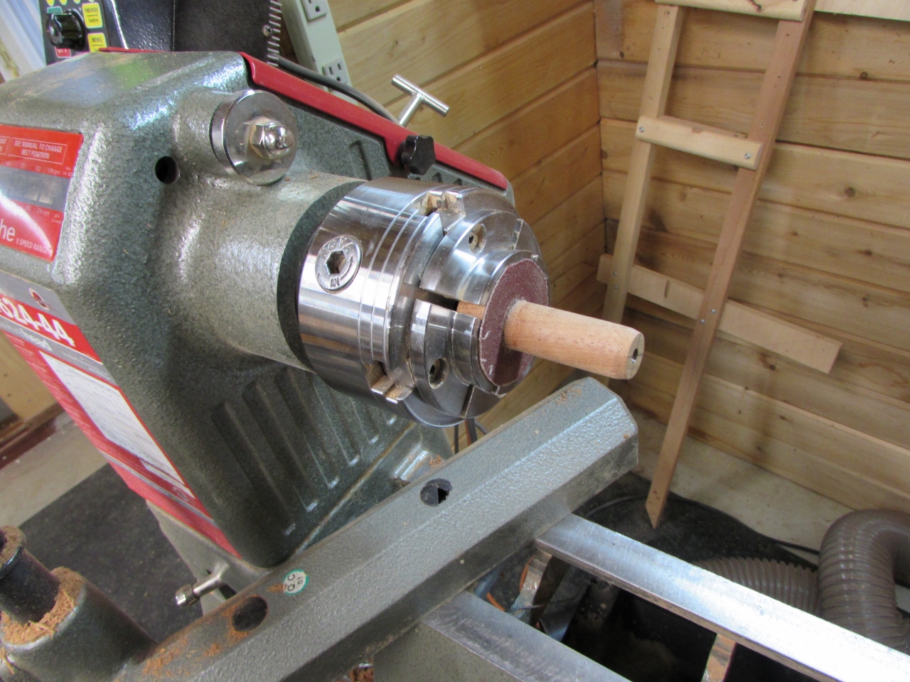
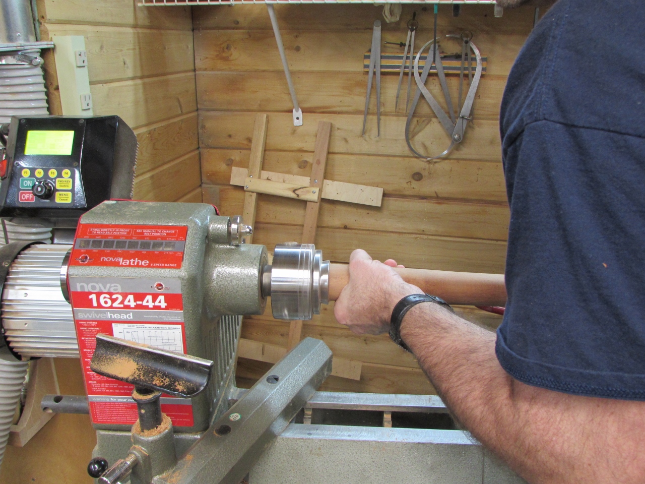
When tightened between centers it creates a friction fit that will allow me to cut it.
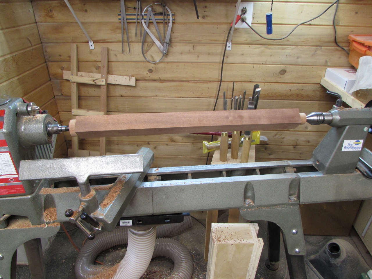
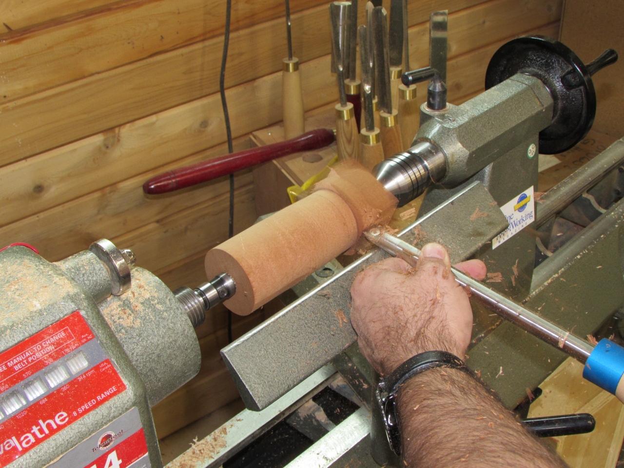
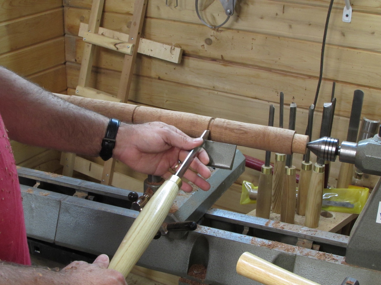
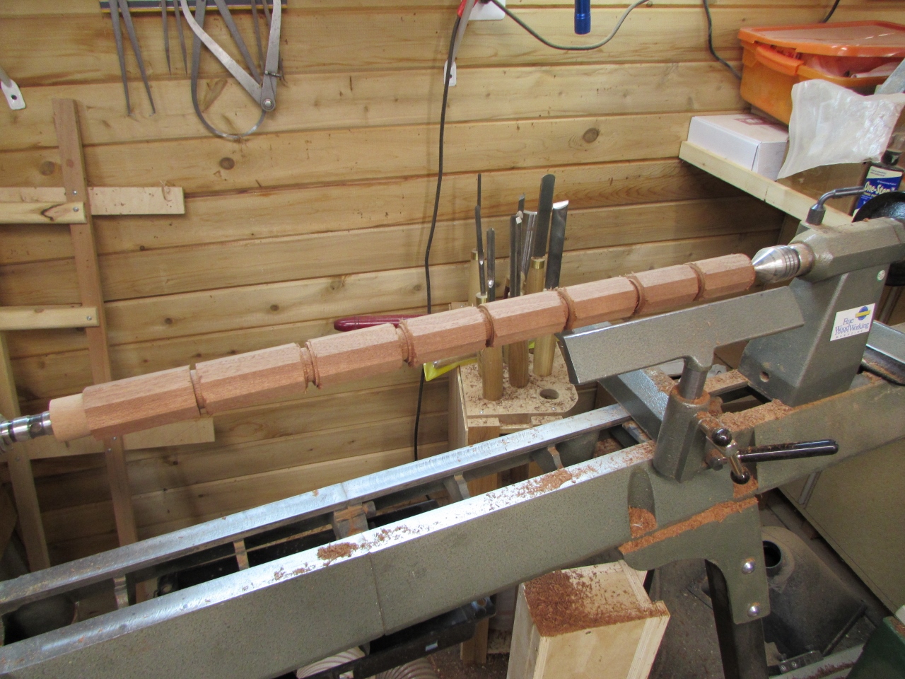
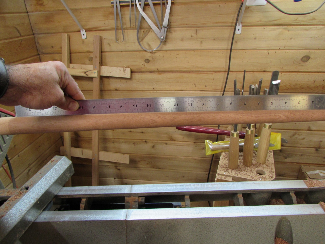
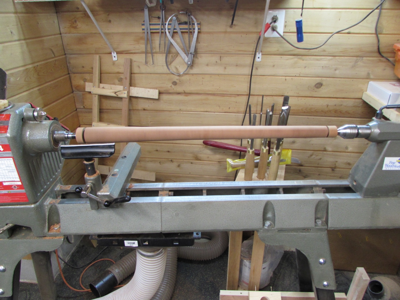
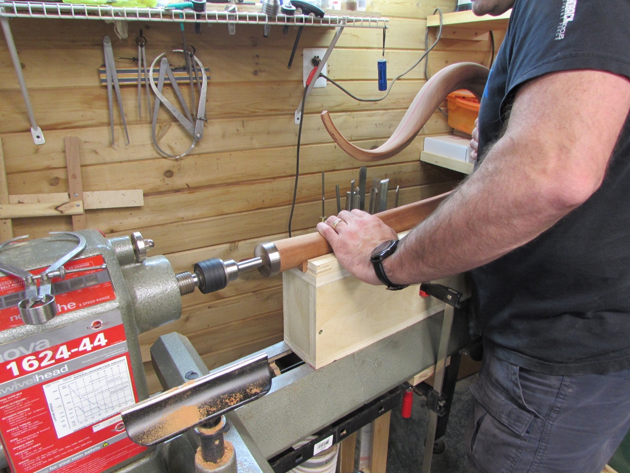
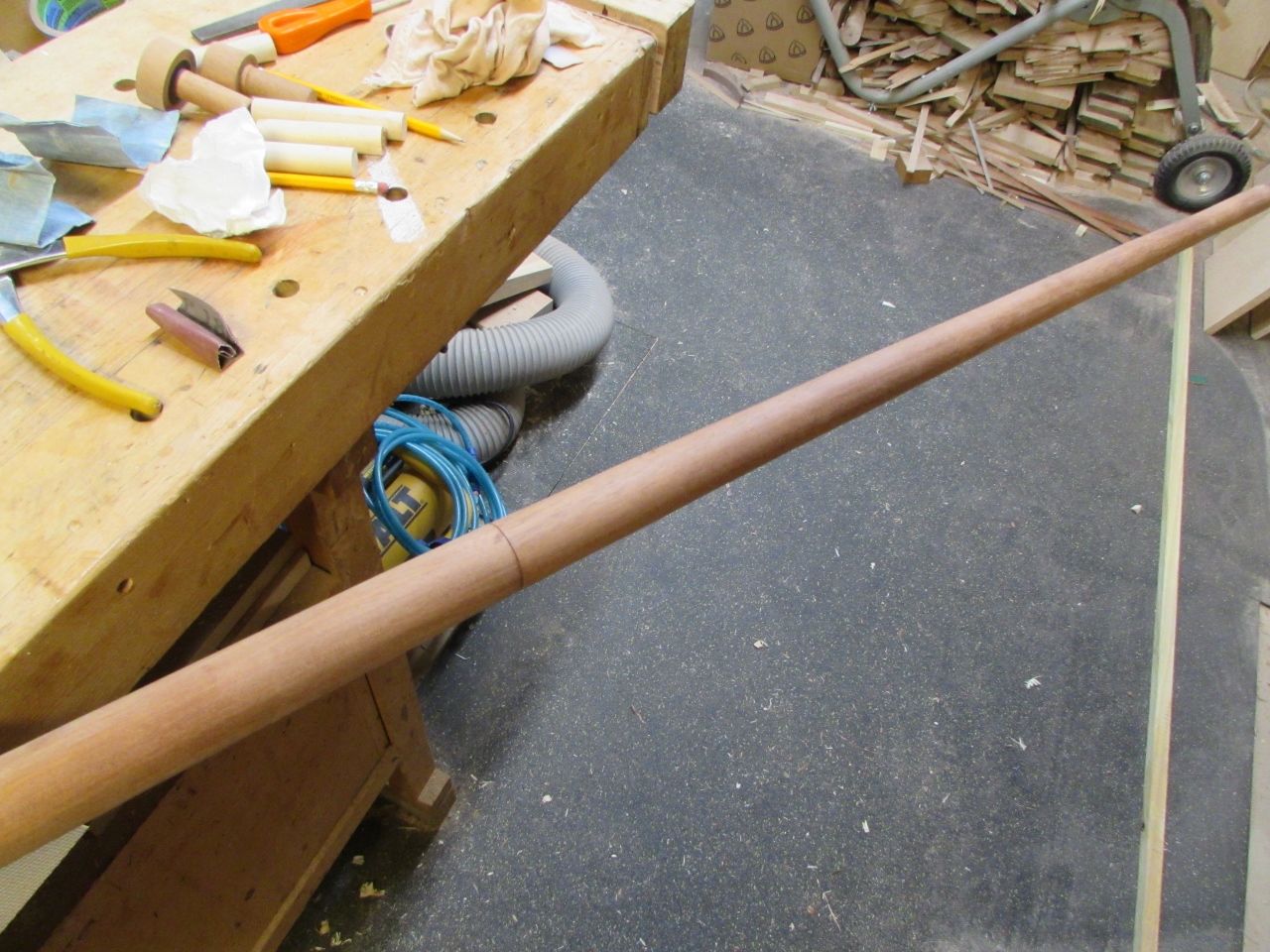
I start by roughing out a cylinder, then I cut the first few inches to exactly match the bushing.
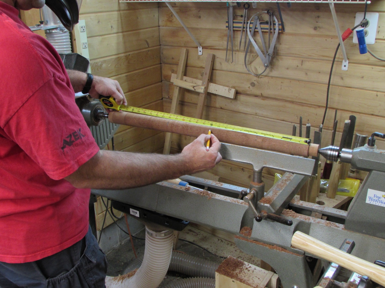
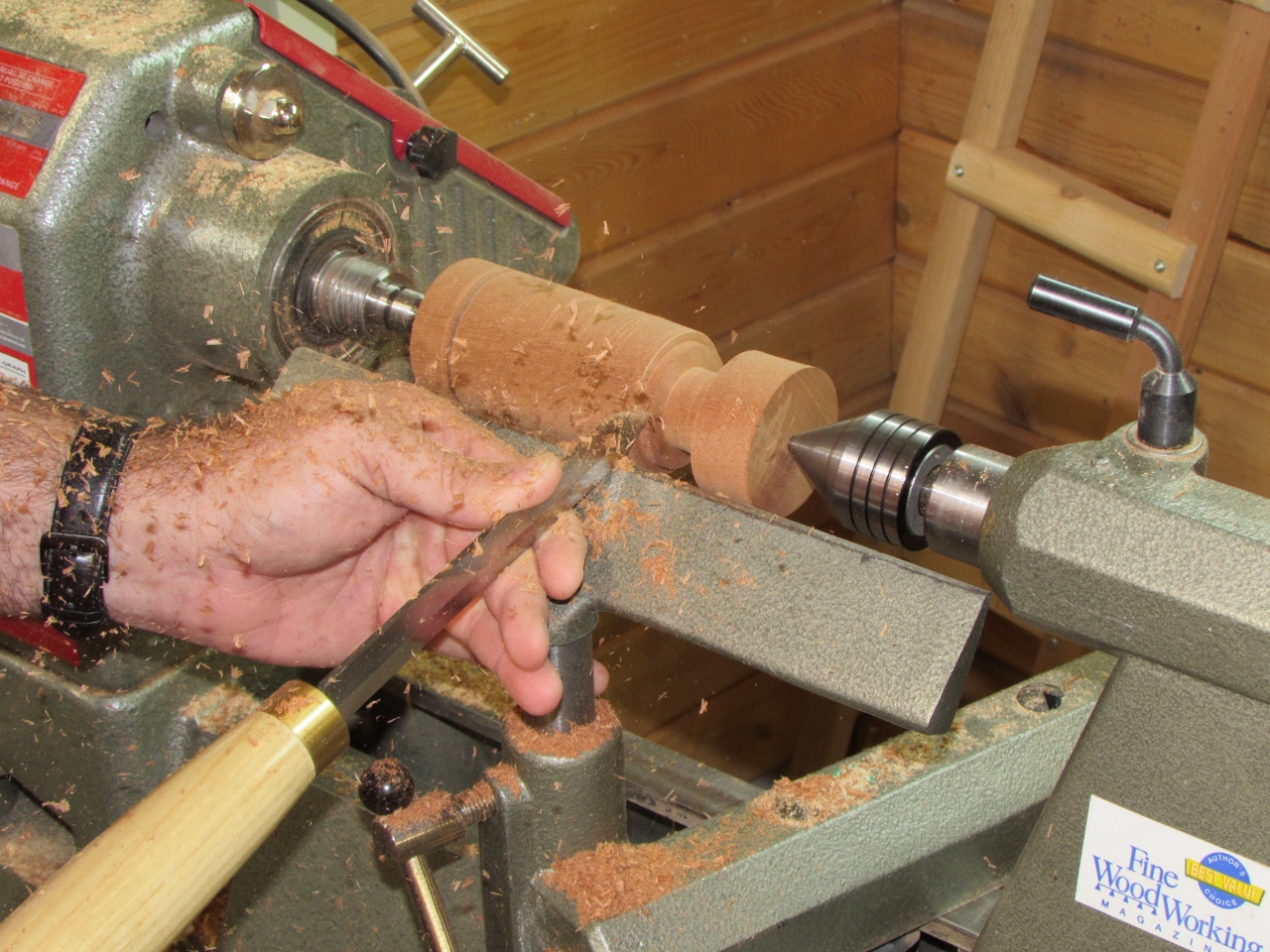
From that point to the other end, I measure and divide the blank into approximately 3″ sections.
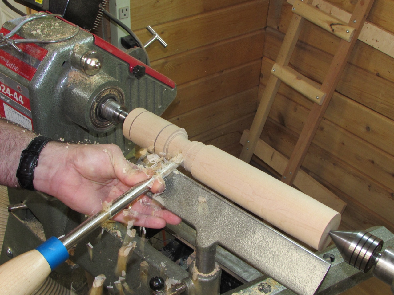
With a little math, I calculated the depth of each getting slightly deeper as I moved to the right.
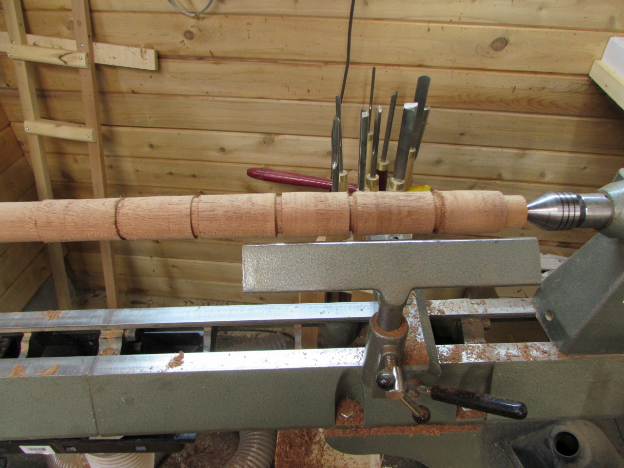
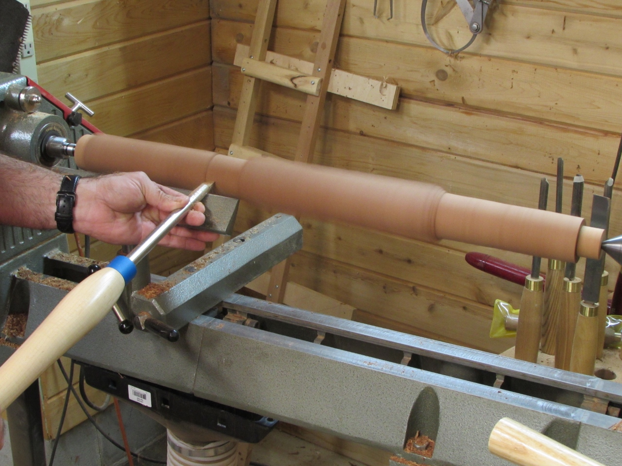
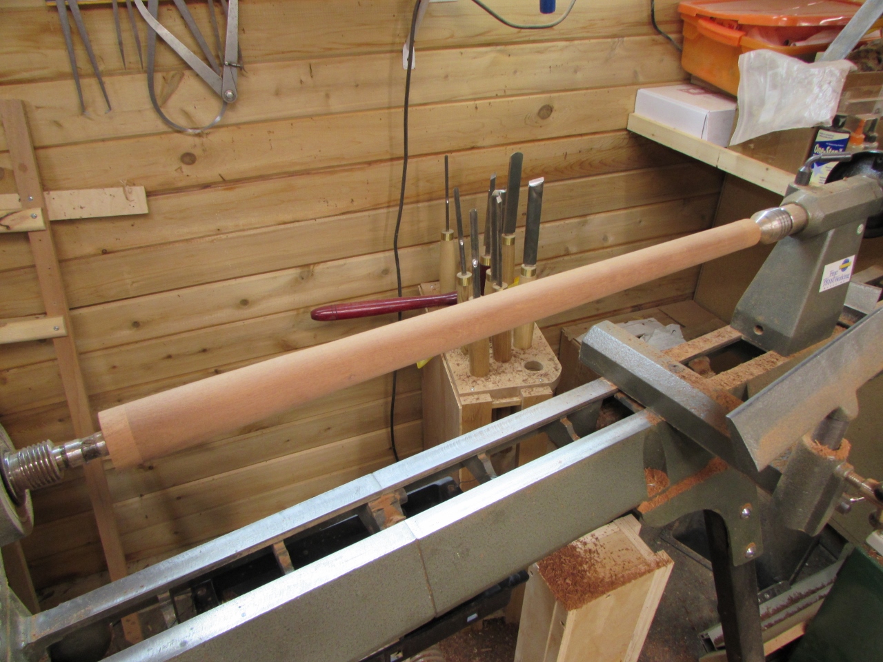
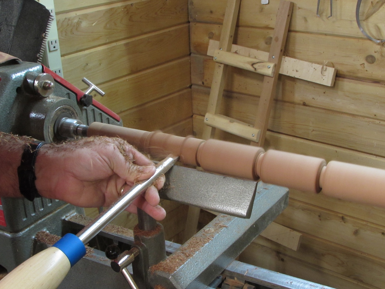
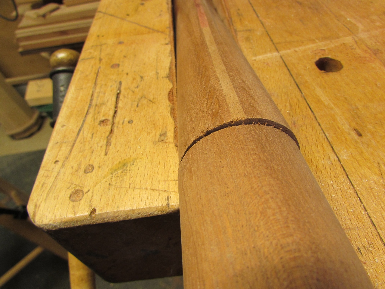
Then I just connected the dots by creating a gentle taper from one cut to the next.
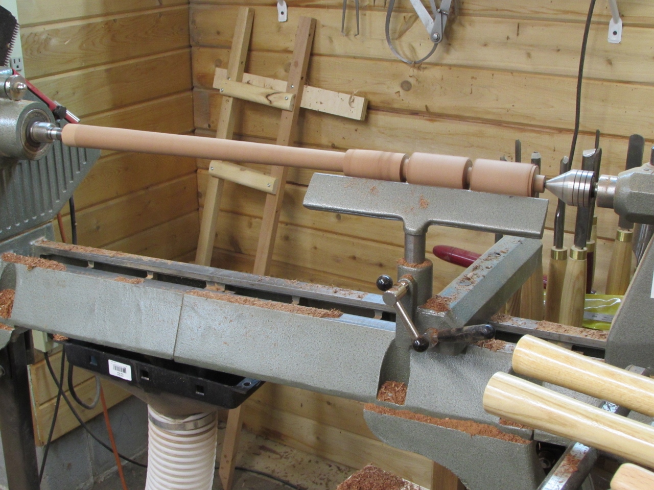
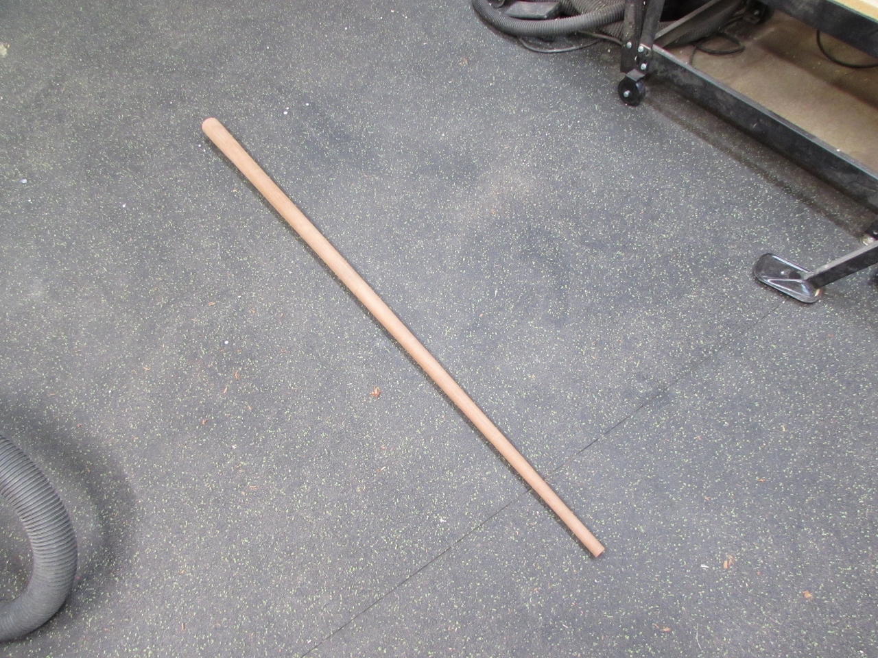
Some sanding and the first section was done.
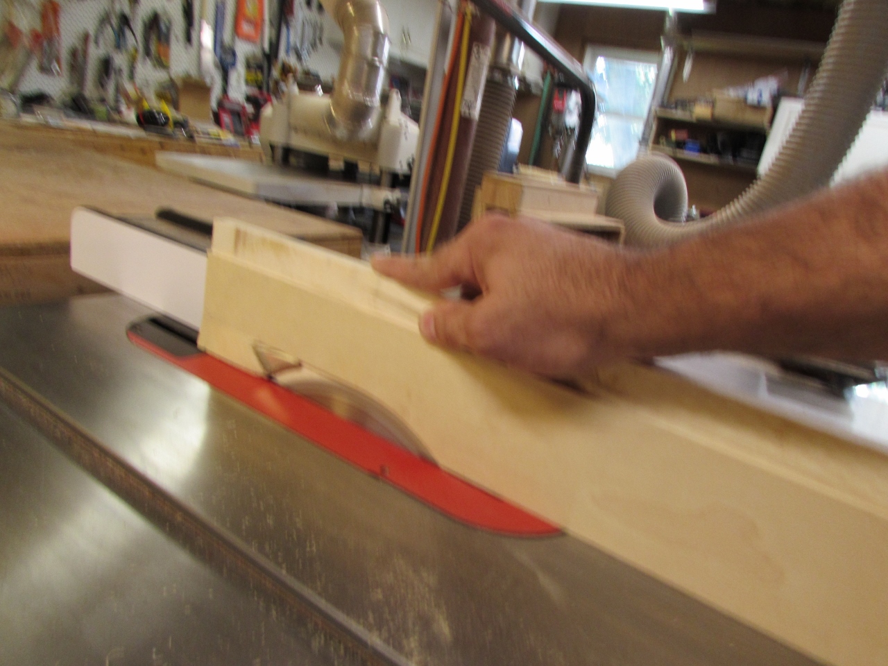
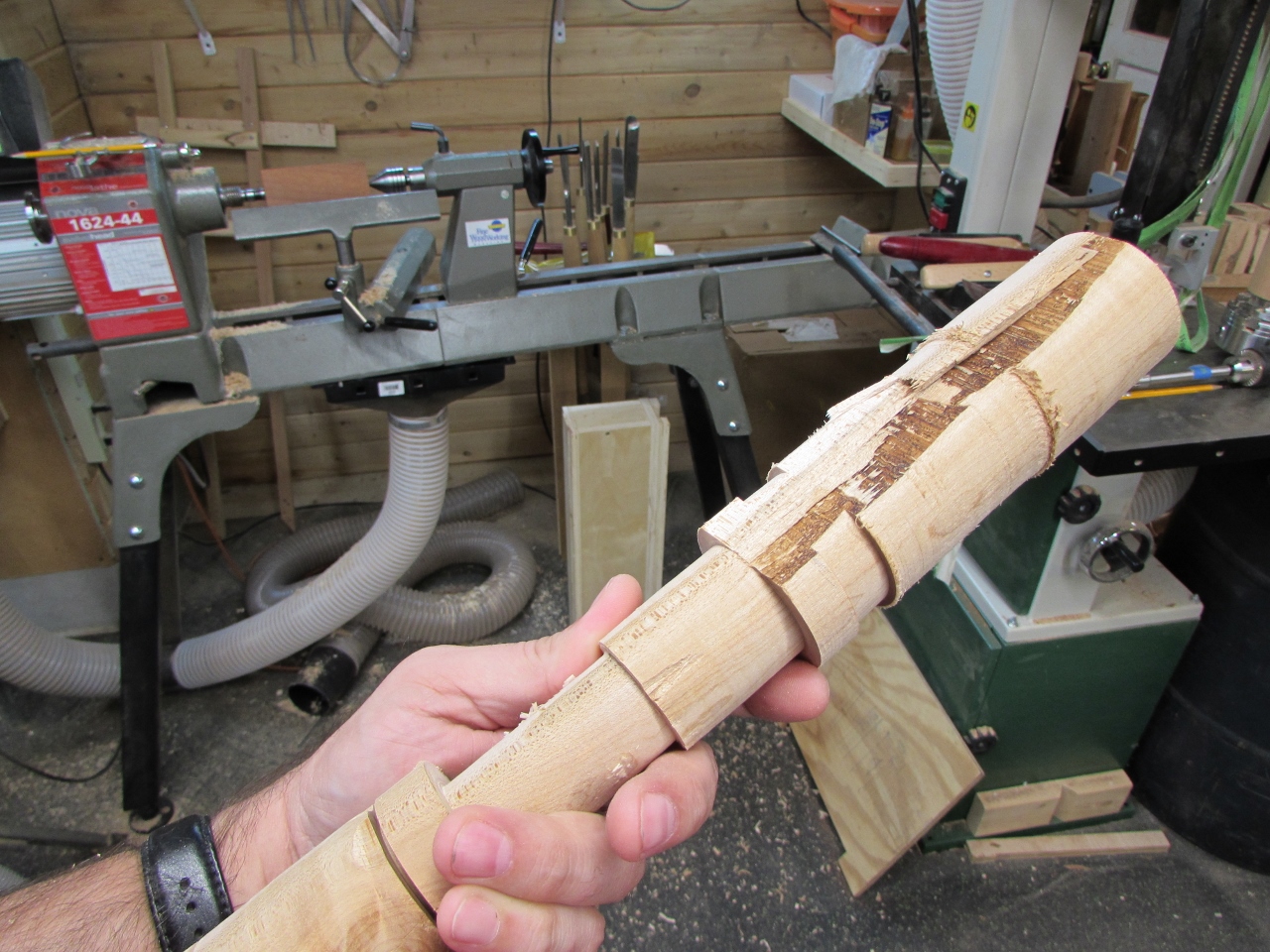
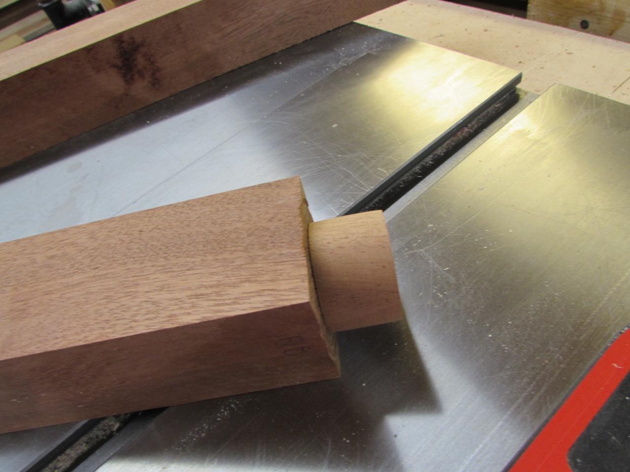
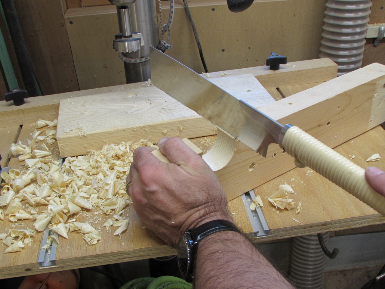
Before cutting down the second leg, I decided to set my table saw blade at a 45 degree angle and remove the corners first.
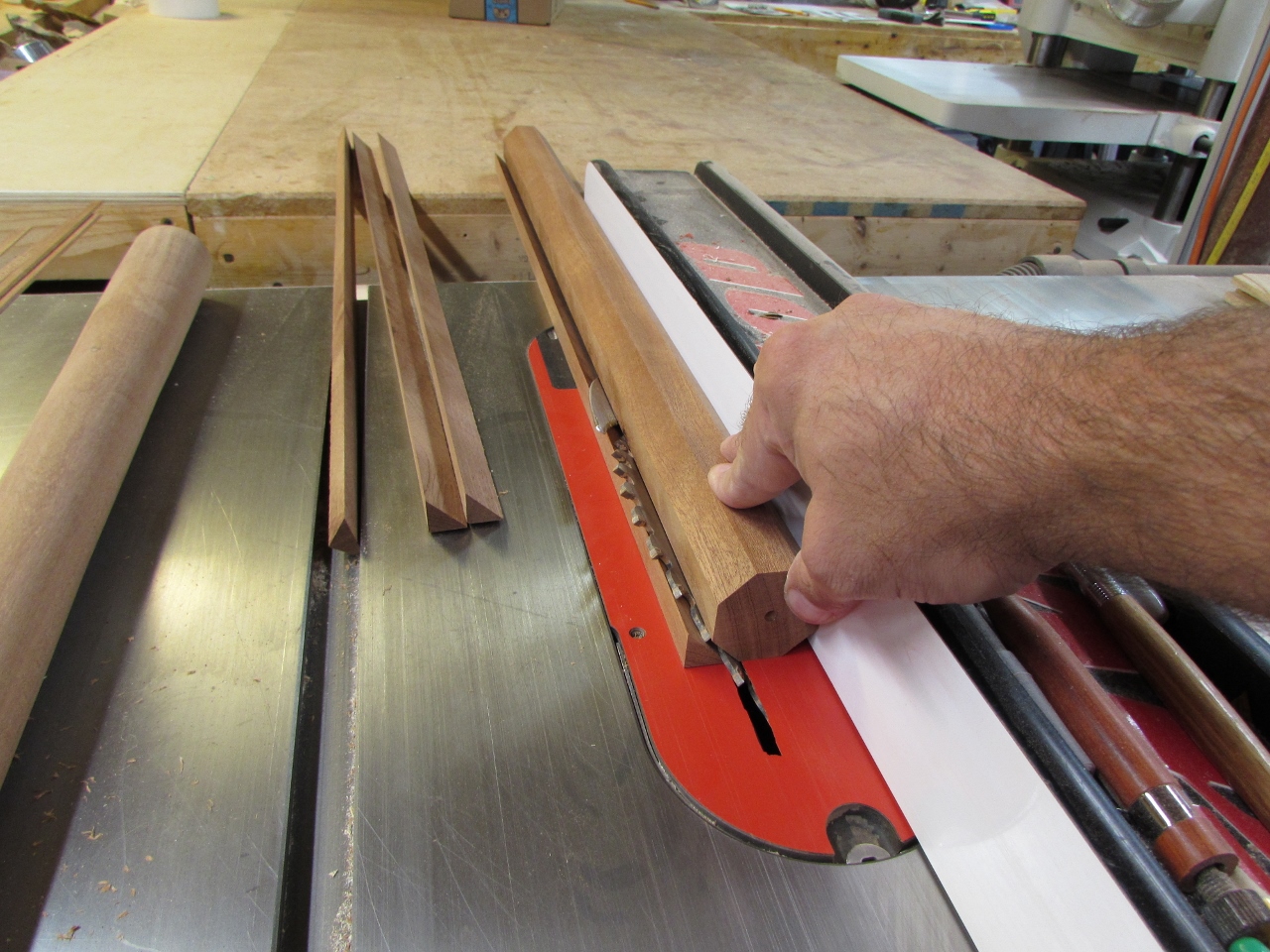
This will save some time, roughing down the blank, and some cleanup later.
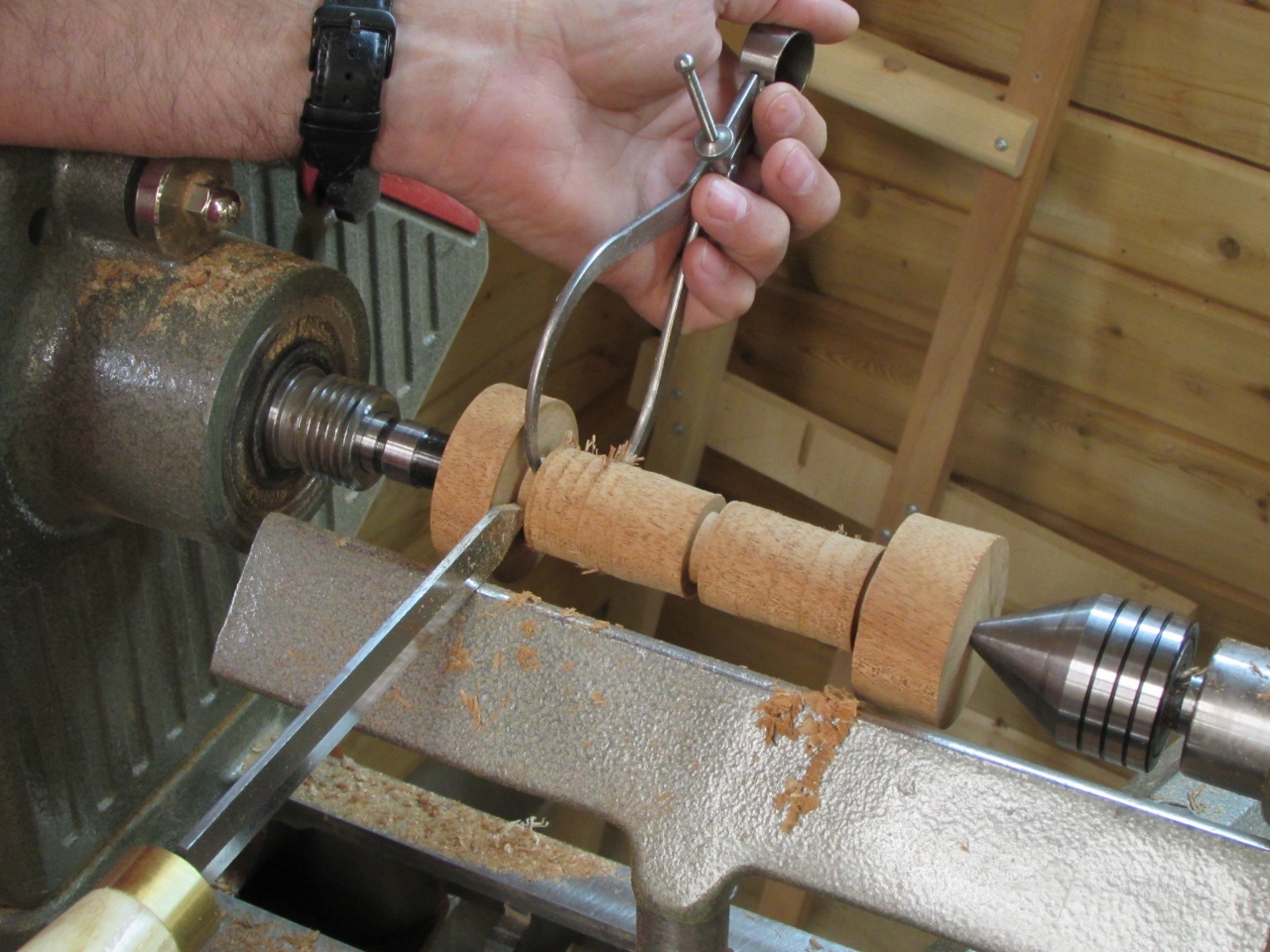
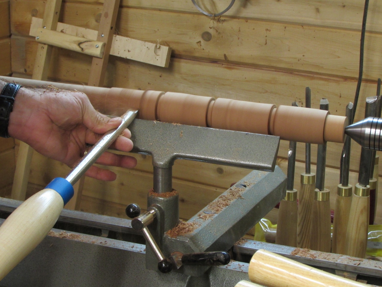
I started this leg by using the smaller of the two bushings on the left and cutting the right side down to 3/4″. Then I marked off every 3″ again and set my graduated depths.
I connected the dots again stepping down from 1-3/8″ down to 3/4″
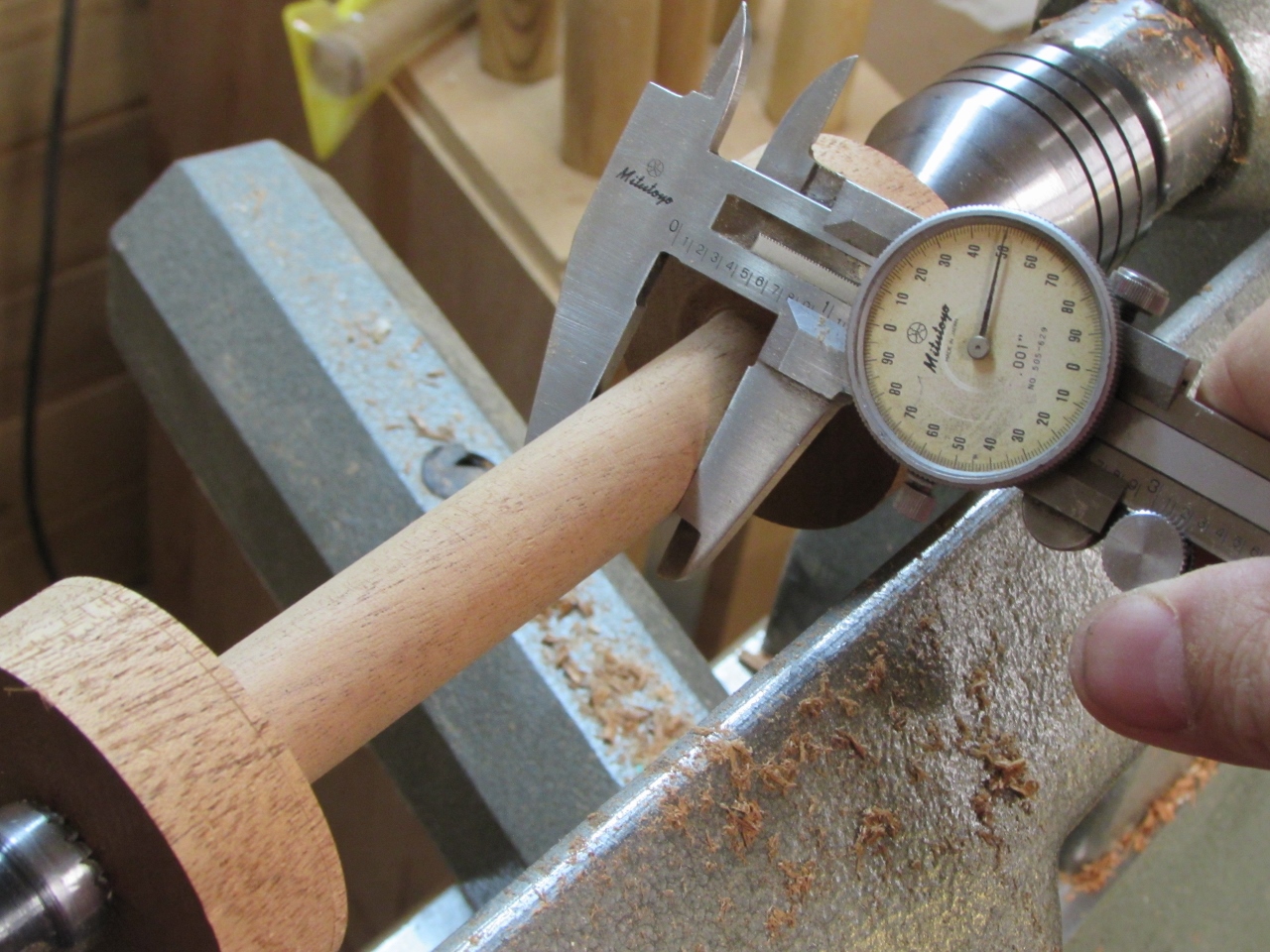
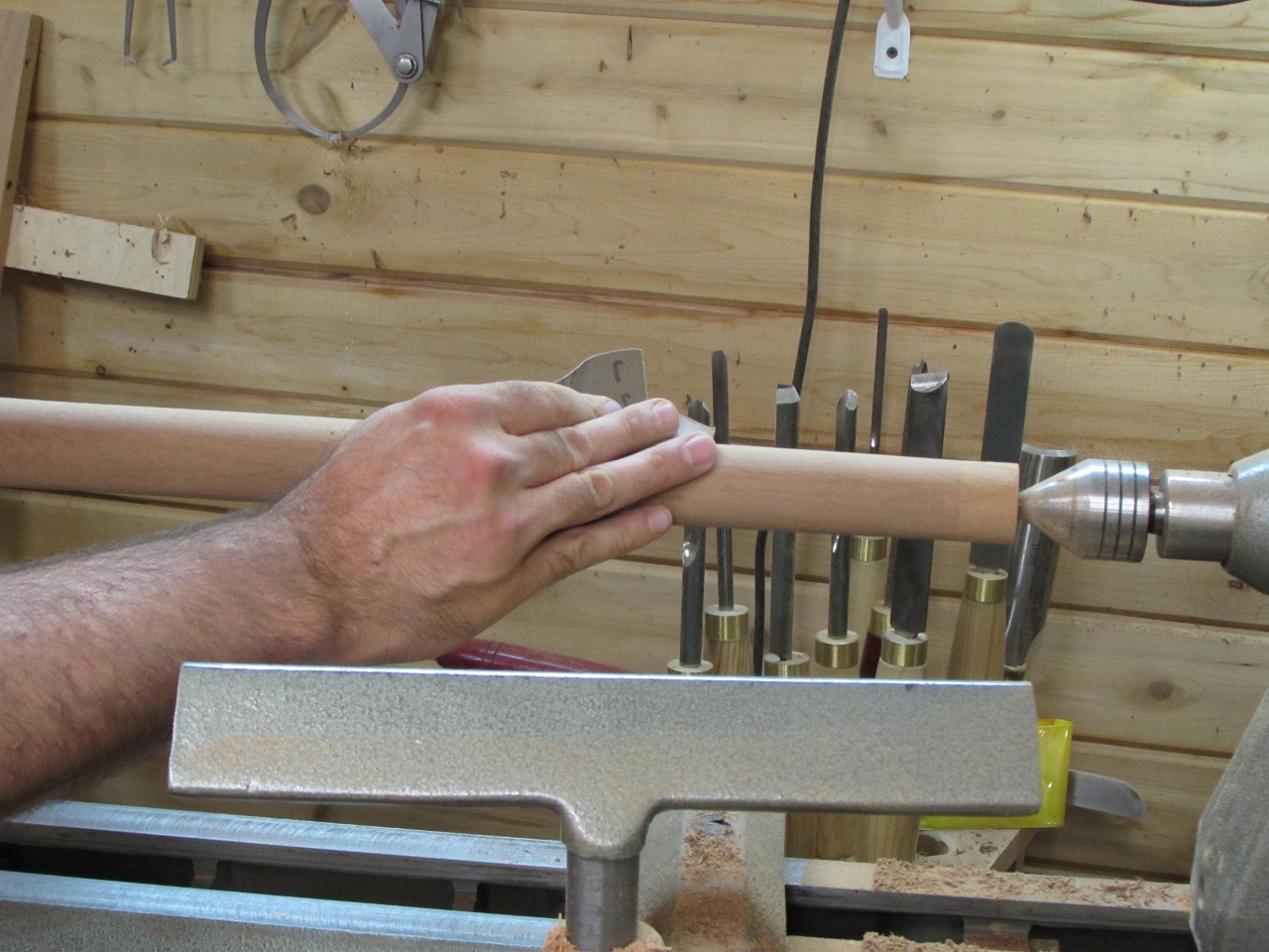
After some cleanup, I checked to see how well I did. Not bad, only a couple of slight dips.
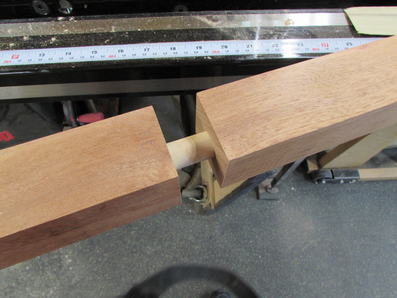
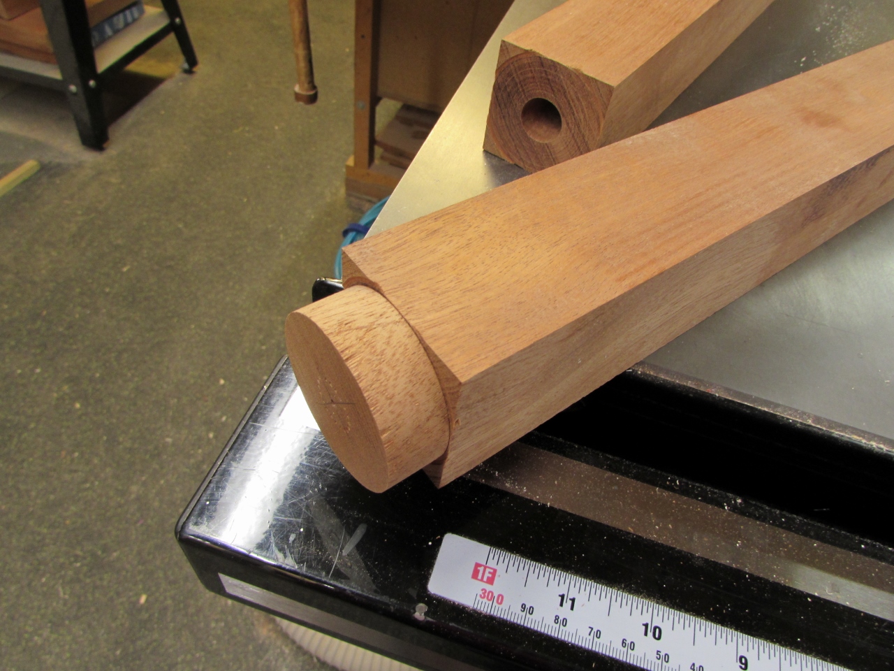
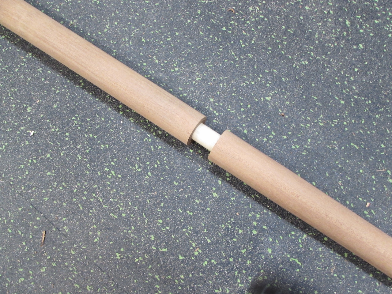
I inserted the 3/4″ dowel again and assembled the legs. It was a good fit, except for the slight angle on the end.
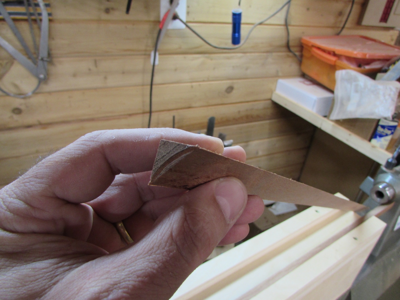
I had a thought about how to better face off the ends, so I made up another bushing.

3/4″ diameter on one side and 3/8″ on the other.
I cut off the bit at the end and then cut out a piece of 100 grit sand paper to mount to the 3/4″ side.
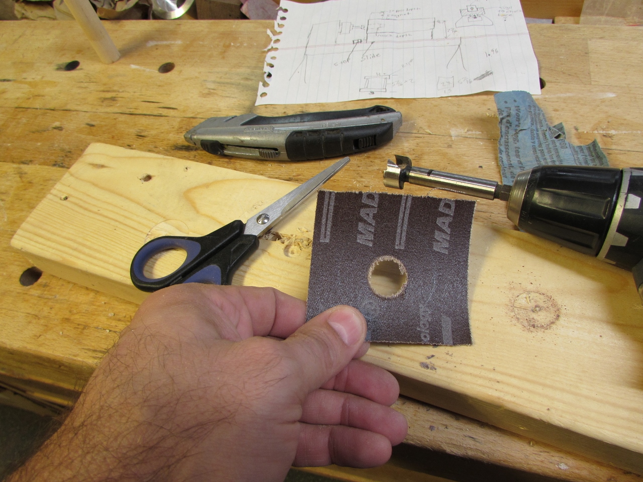
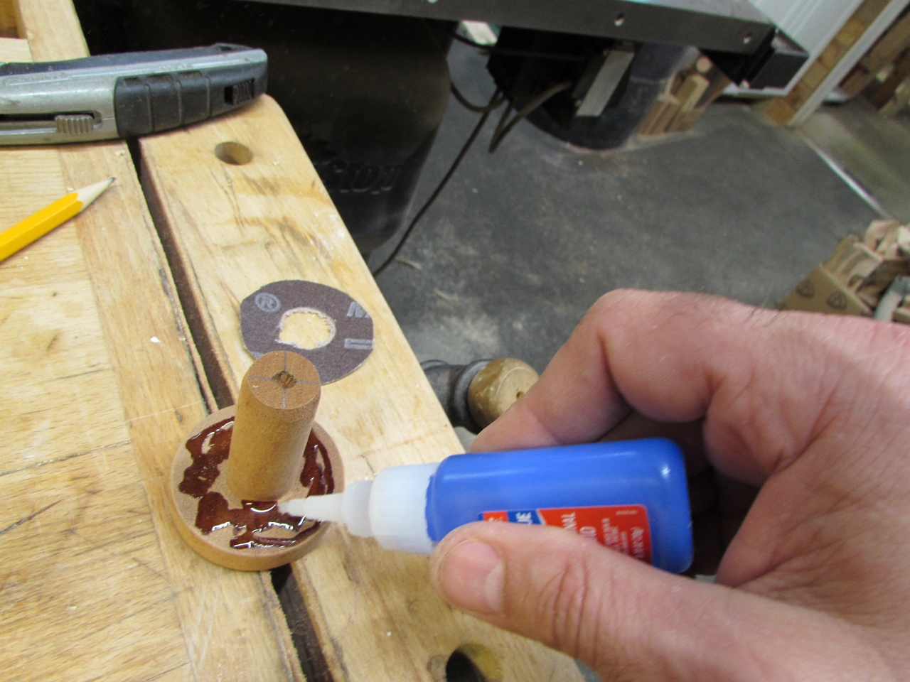
I used a bit of CA glue to attach the abrasive.
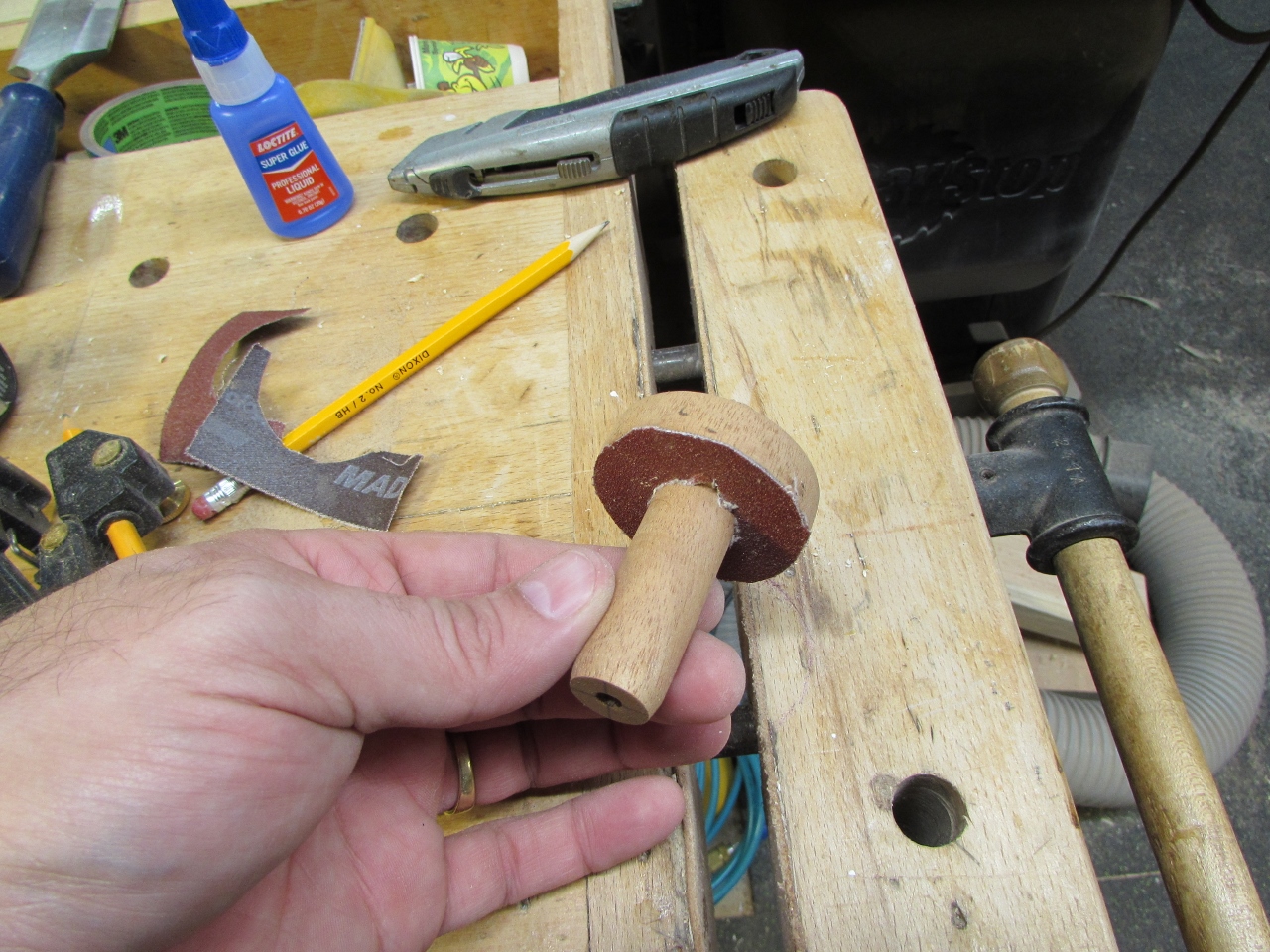
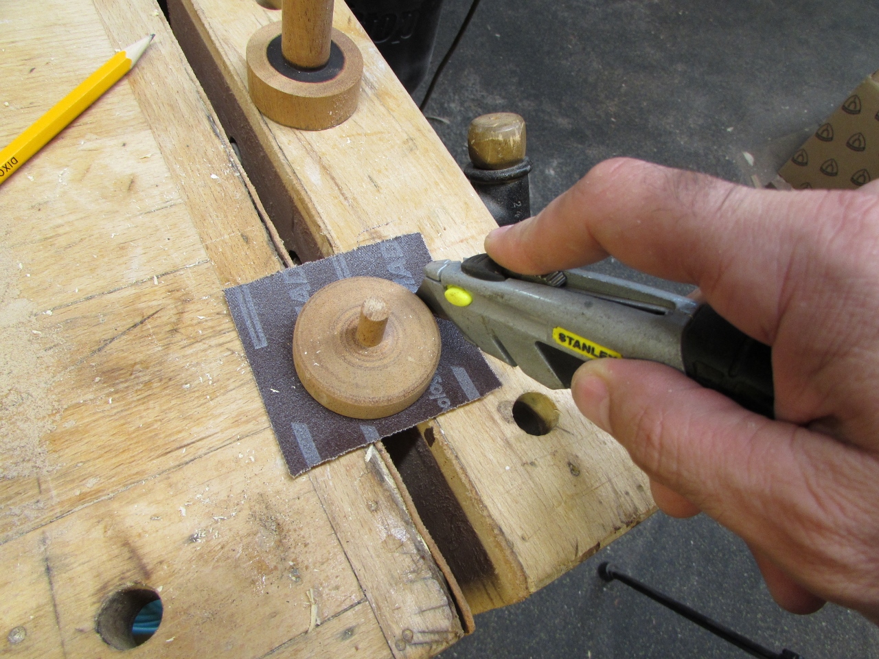
I placed the 3/8″ side into my drill and spun it up, trying to face off the end.
My thought was that the tight tolerance on the 3/4″ side would keep everything lined up so the abrasive could flatten the end.
You can see that it started to work but I promptly broke off the smaller side. This would work better made from metal.
Giving it one more chance, I set it up in the lathe head and tried to finish, but my arm wasn’t steady enough to be really accurate.

So I moved on to plan “C”. I kicked around the problem with Dave and his friend Bill, and Bill came up with the idea of installing some spacers and reusing the bushings.
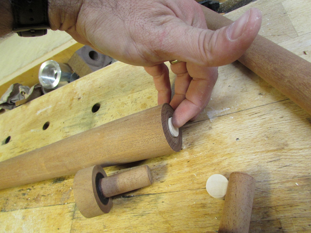
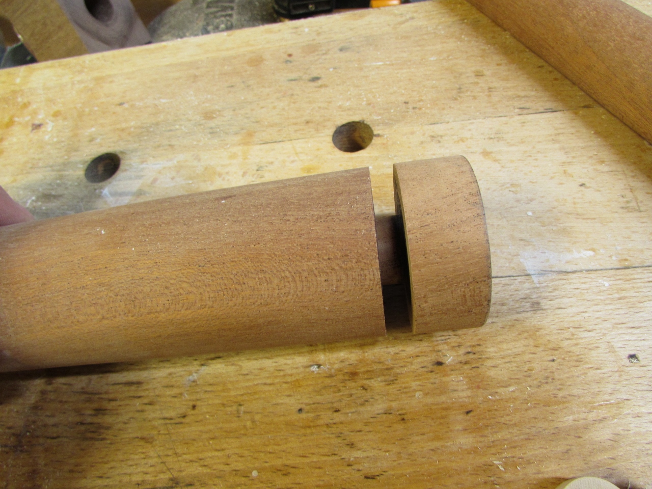
This left a small gap on either side so I could use a parting tool to create a slight under-cut on each face.

The face doesn’t have to be perpendicular to the center, I could eyeball the cut if I made it slightly concave. Then, when butted together, only the edges would touch and they would be perpendicular to the center. It worked perfectly!

Now for the hard part that I have been putting off. I have to face and drill the hole in the end of the head-piece.
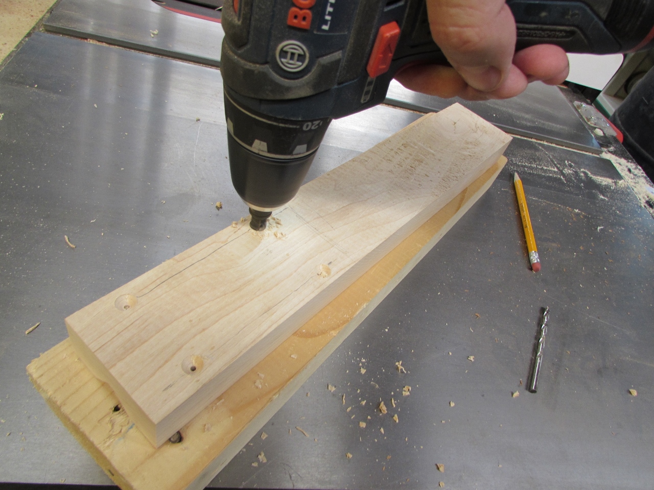
I am going to have to modify my jig to hold it, but I need the clamps to be out of the way.
So I drilled a hole on either side, then cut the bottom side of them flat.

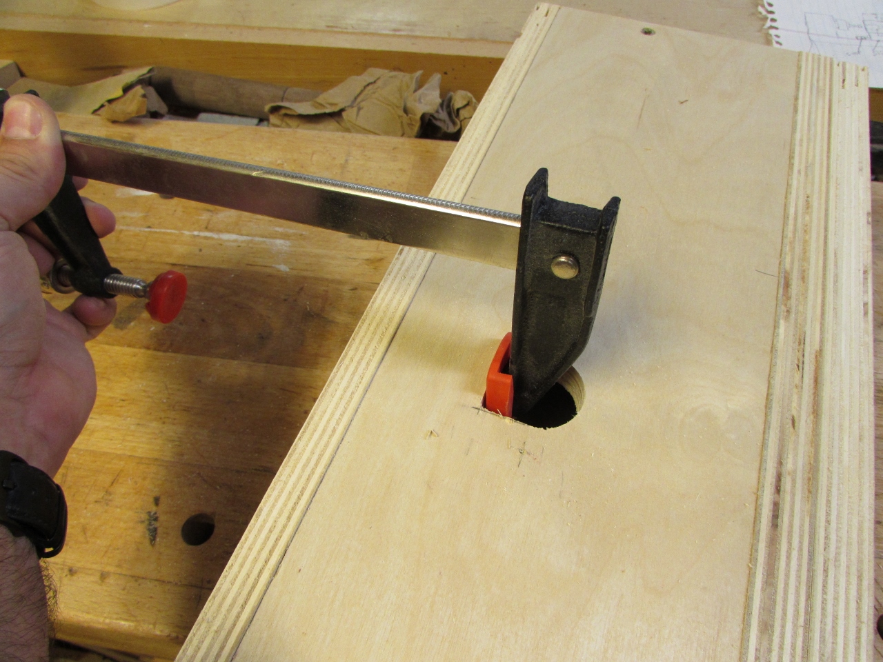
This gives me a lower opening for my clamp.
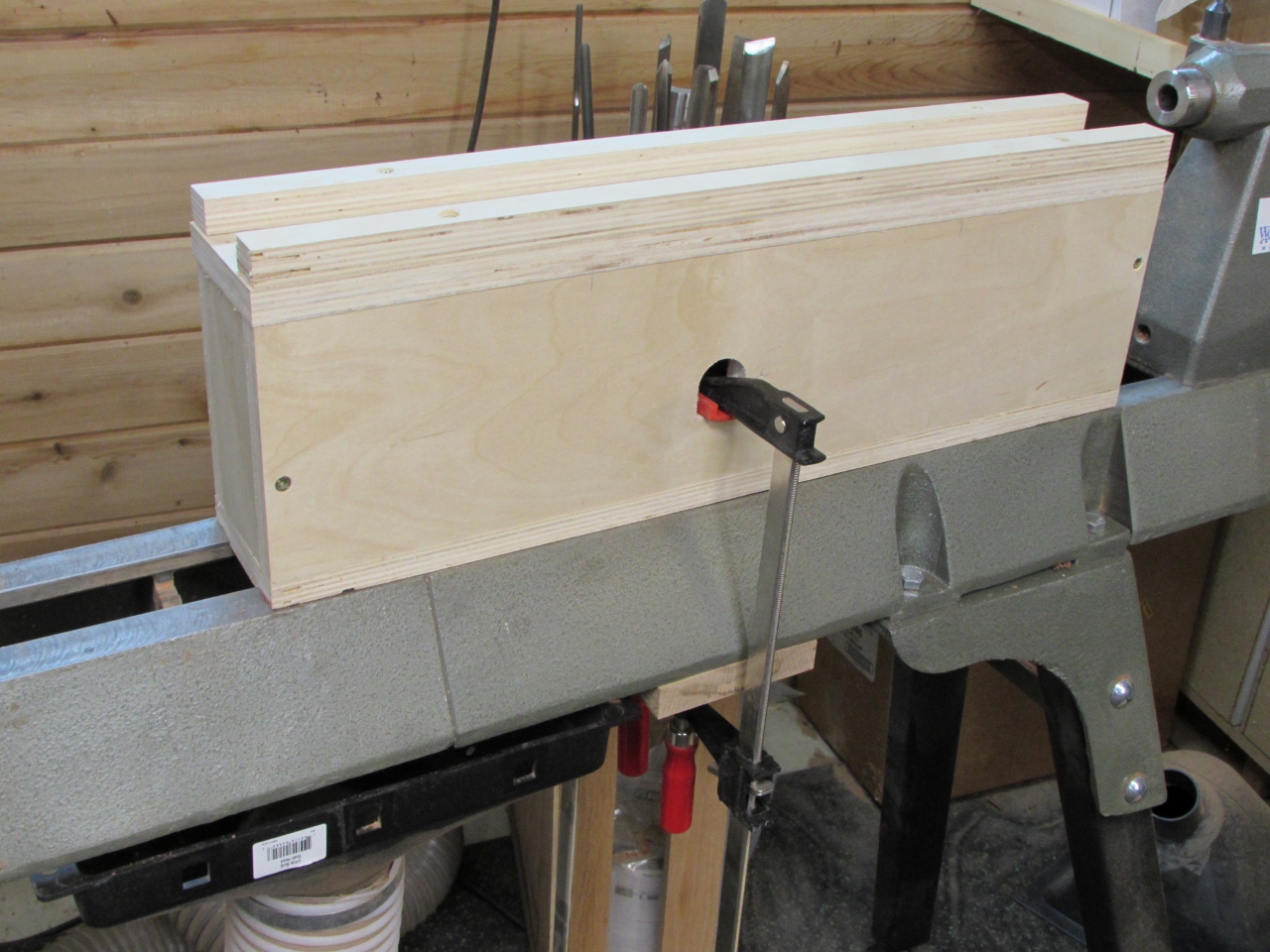
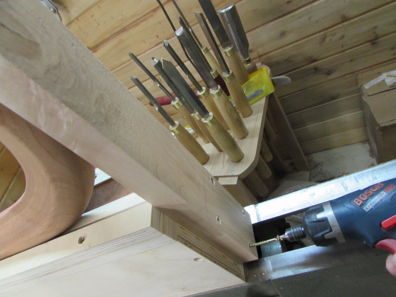
I used a board to span the bottom of the lathe bed, and clamped the box down.
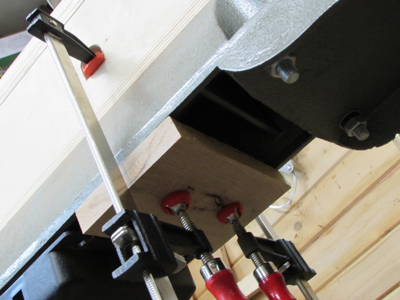
I remembered having those corner off-cuts in my scrap pile, so I grabbed them and inserted them in the bottom of the channel.
They were the perfect size to cradle the head-piece.
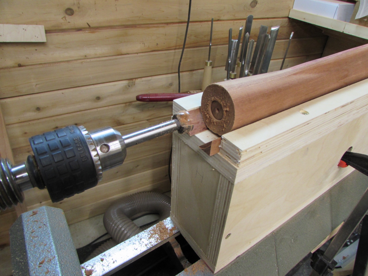
Hoping that would be good enough, I installed the large forstener bit this time, and used it to face the end.
Still a little chattery, but not bad.
When I switched bits, the problem was trying to get enough leverage to push the piece onto the smaller 3/4″ bit. It just wasn’t happening.

So I grabbed a 1-1/8″ thick piece of hard maple and cut a Vee groove into it.
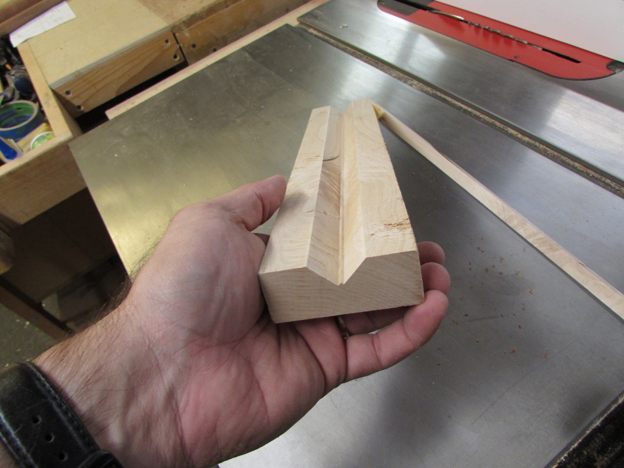
Then I drilled and mounted it to the end of my box jig.
My hope is that it will be rigid enough to be driven by the tail stock.
To help hold down the head-piece, I cut a piece of 2″x4″ to fit over the end and used a couple of 3″ screws to hold it tight.
And of course, I had to pull off the clamps I just installed because the whole thing needs to move as one now.
I probably should have made a second block to clamp down the head, further up, but I was able to hold it down by hand.
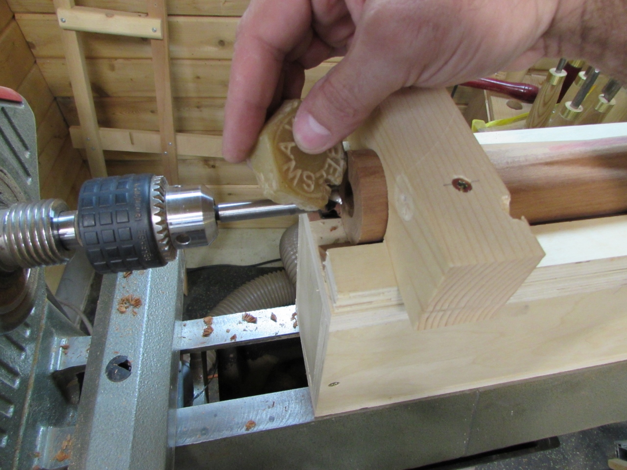
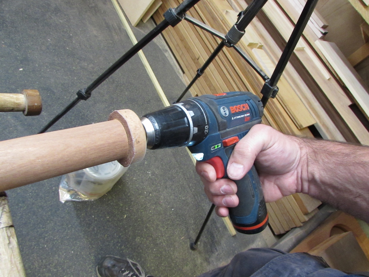
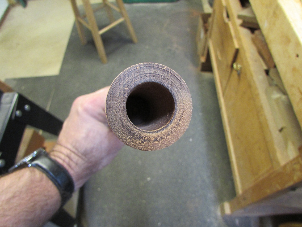
It drilled out the end surprisingly well. As the bit heated up, I applied a bit of bee’s wax to the cutting end to help lubricate it. It cuts a lot better that way, but the wax collects dust so you have to empty the hole out more often.
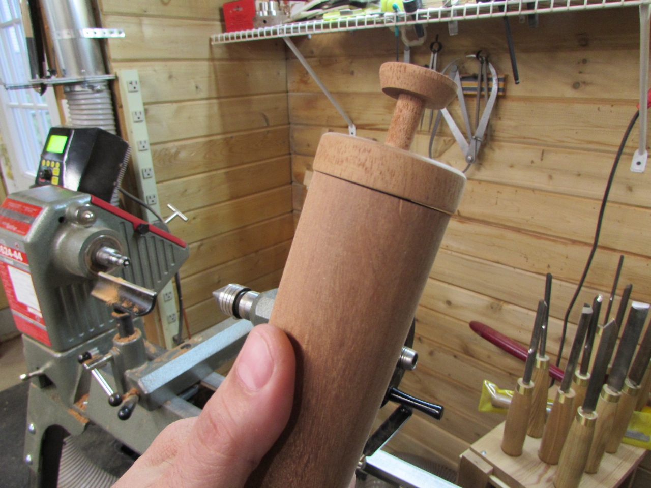
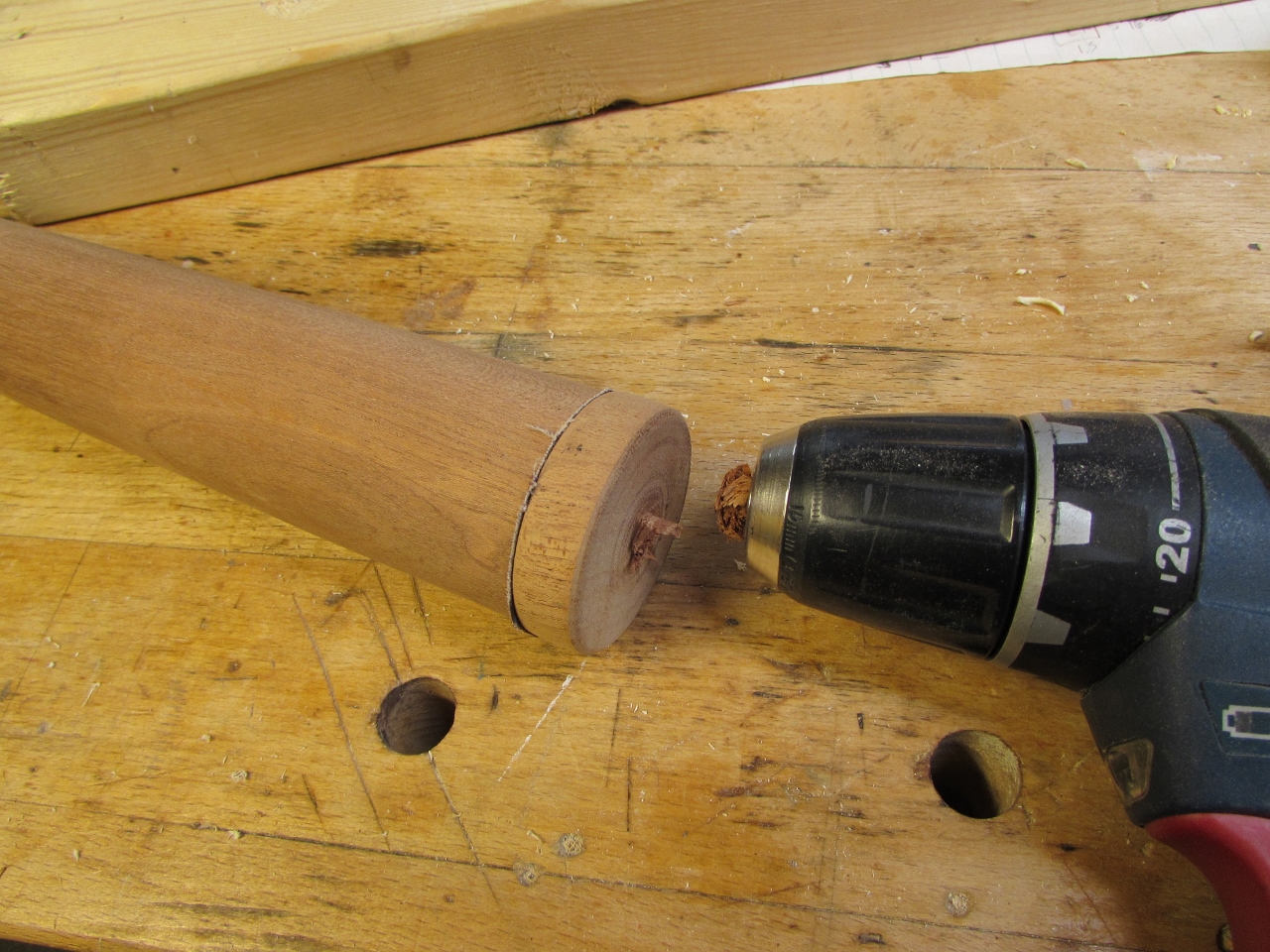
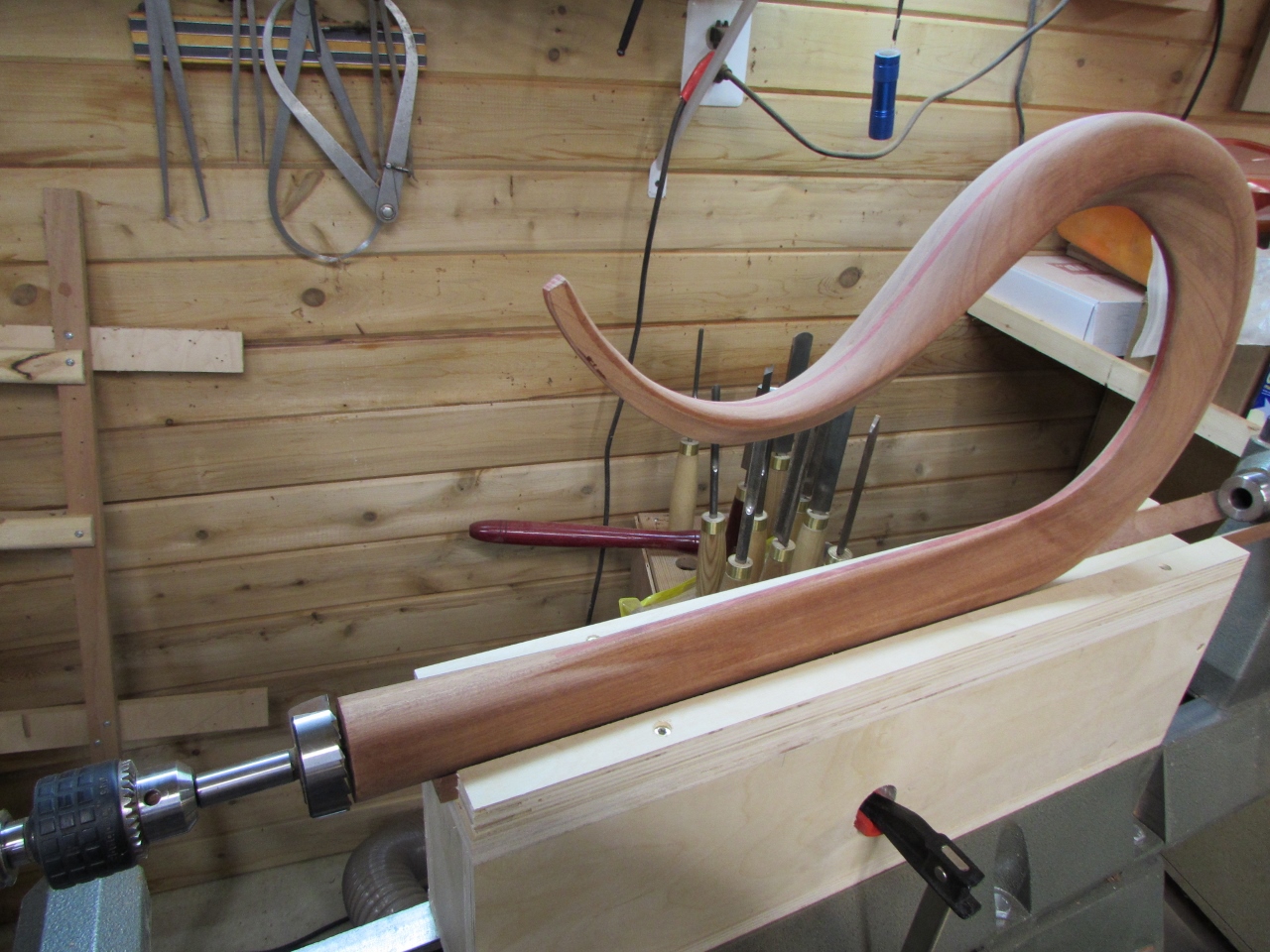
I grabbed my wood dowel and did a test fit to the leg. It may not look like it, but it was a surprisingly good fit.
The head-piece is slightly over-sized still and slightly out of round.
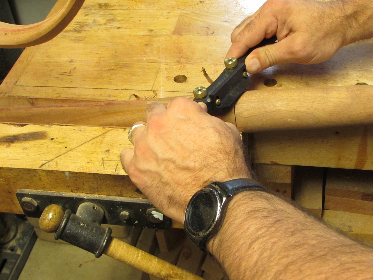
I used a spoke-shave and a block plane to take it down to the correct shape and size.
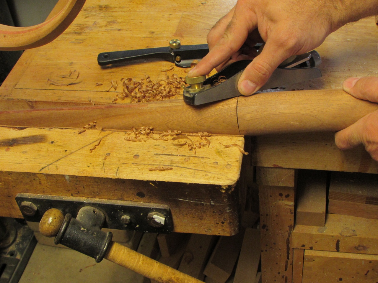

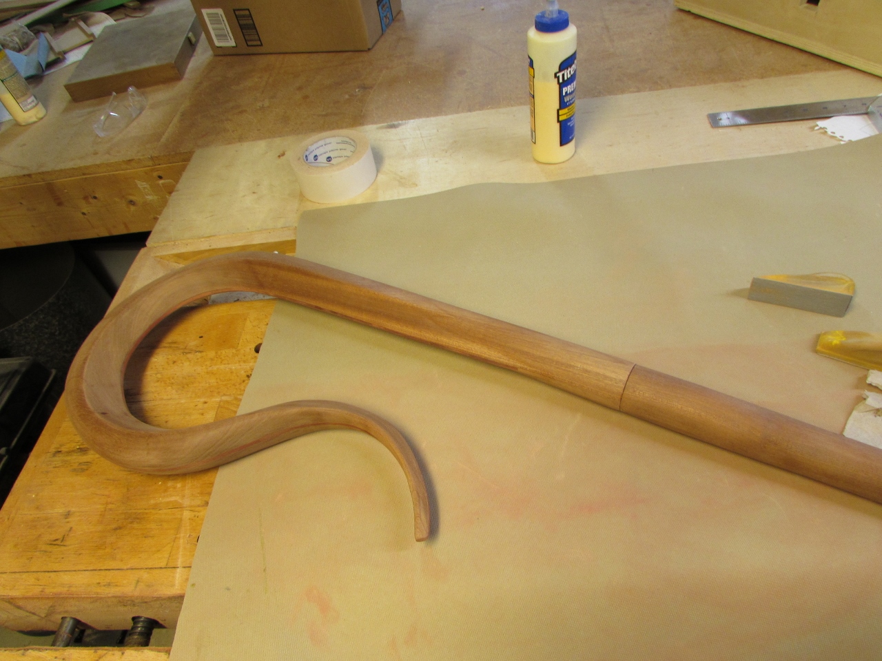
And there you have it. everything fits!

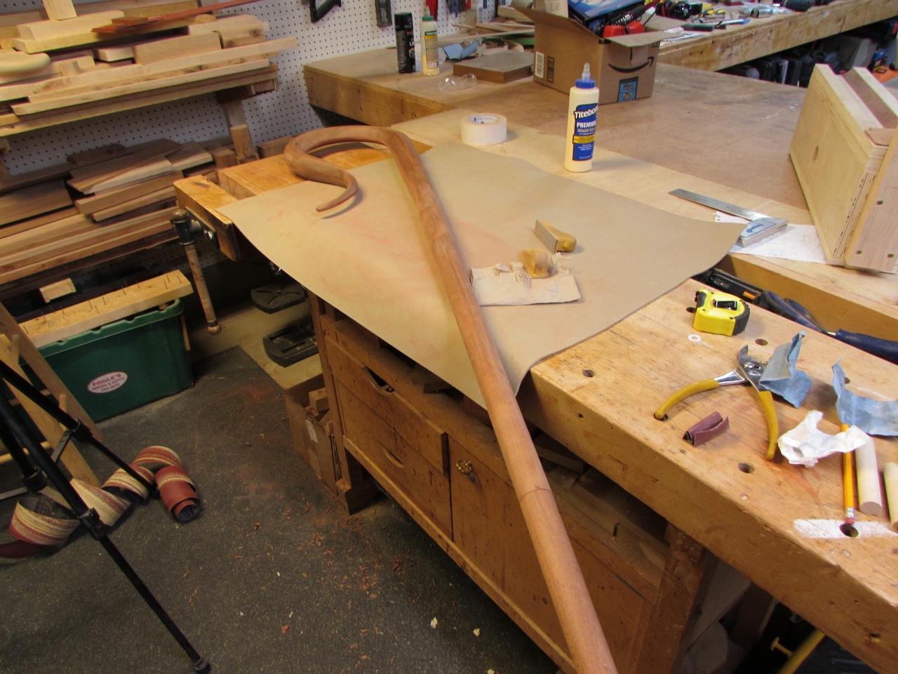
I spent a good deal of time hand sanding the CNC mill marks off of the head-piece.
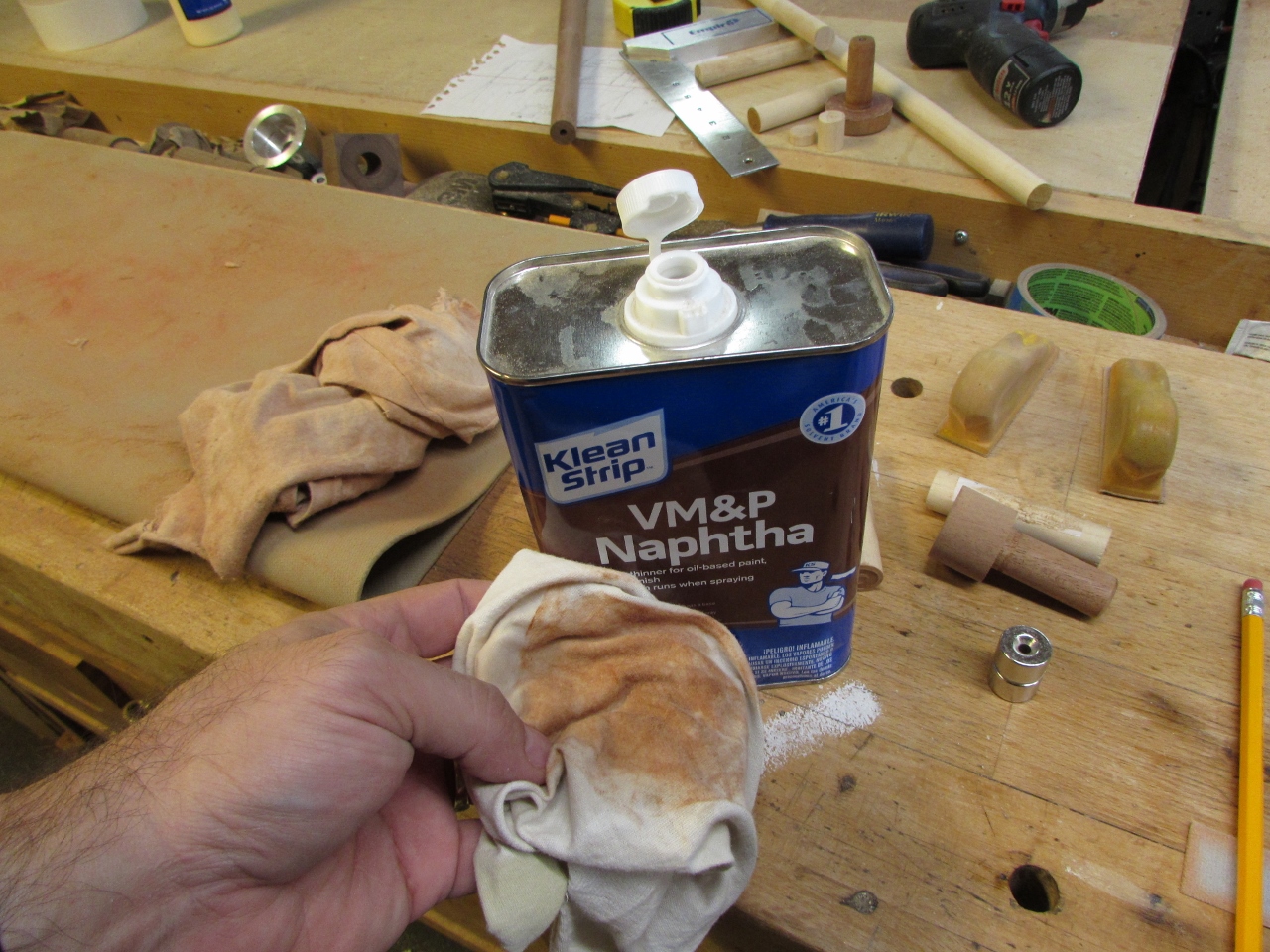
Then I cleaned it up with a little bit of naphtha to see what the final finished product would be.
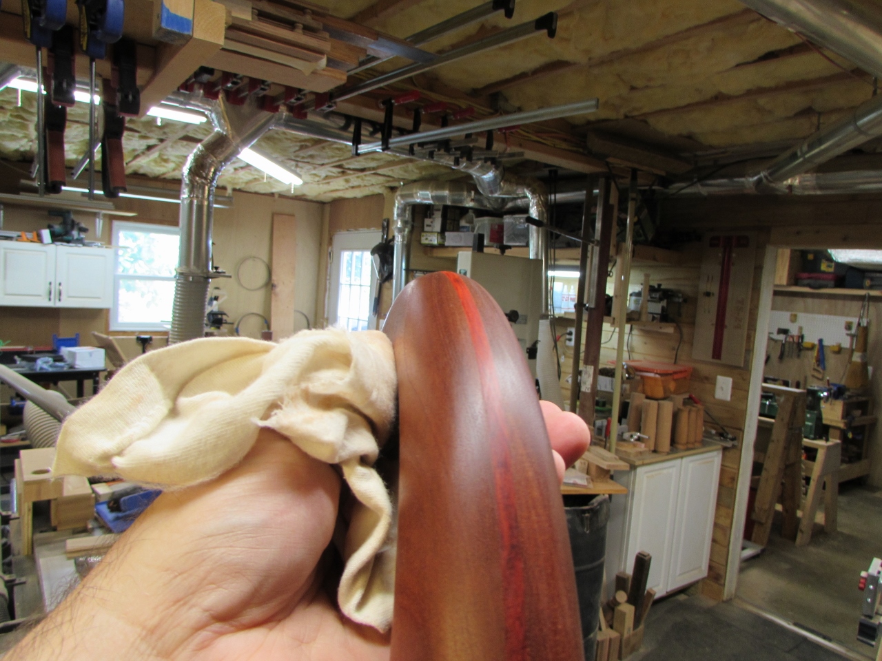
Its darker than I thought it would be, but it still looks nice.
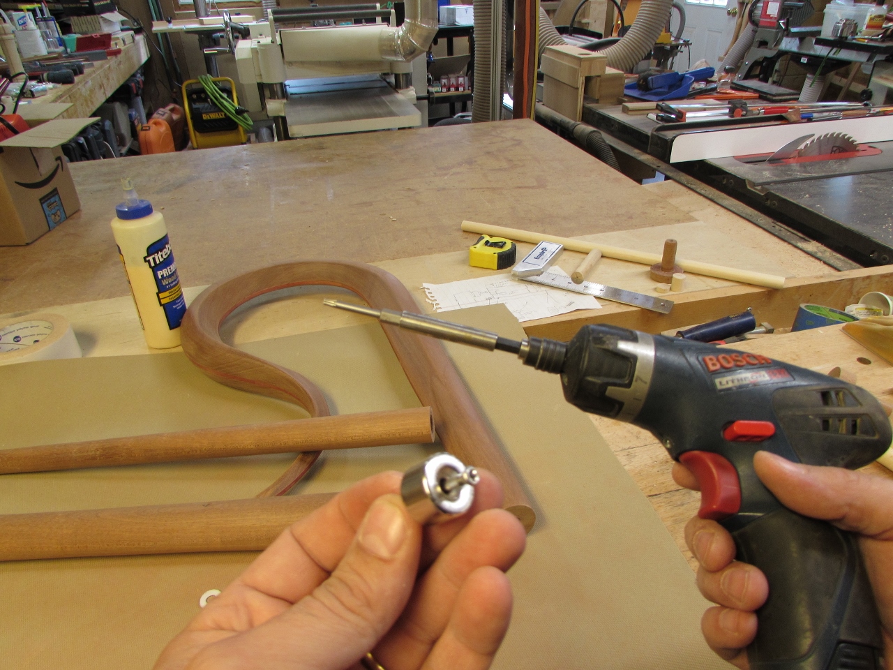
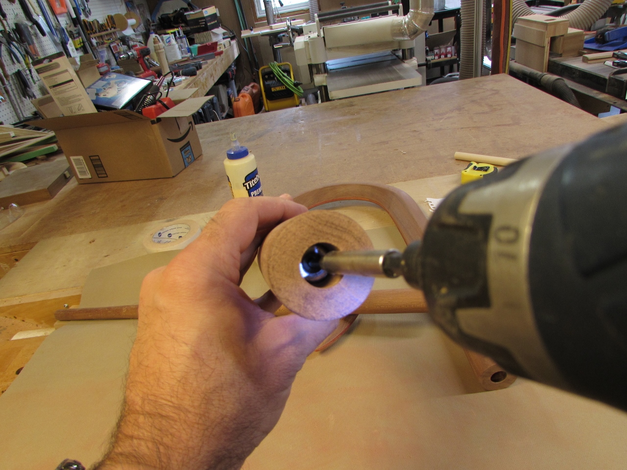
Finally it was time to install the connection hardware. I am using 3/4″ diameter neodymium magnets with an approximate 30 pound pull. I am installing them with a small head stainless steel screw. Mainly because that is the only screw that I have that sinks below the surface when installed. You have to be careful with stainless, they can break if over tightened. The magnets go into the top of the two leg pieces. Those holes were drilled 1/2″ deeper to accommodate the magnets.
To connect to the magnets, I am using 3/4″ steel rod, cut exactly 4″ long. I had a machinist friend face and chamfer each end, then place some course threads about 1-3/4″ up on one side. I had to do a bit of filing to clean up the burrs and make sure the diameter stayed at 3/4″.
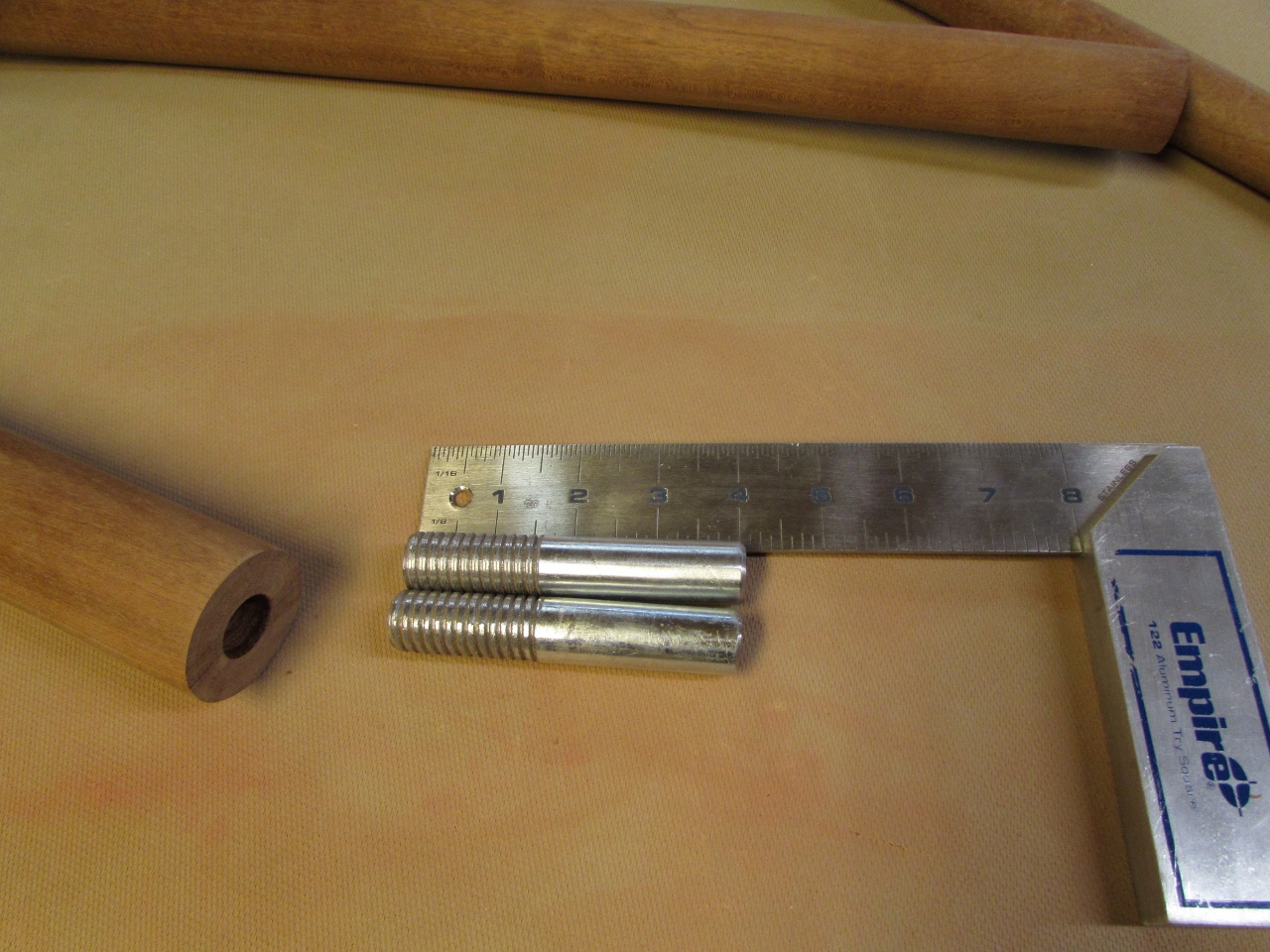
The purpose of the threads is to have a place for the epoxy to go, and lock everything in, once the epoxy hardens.
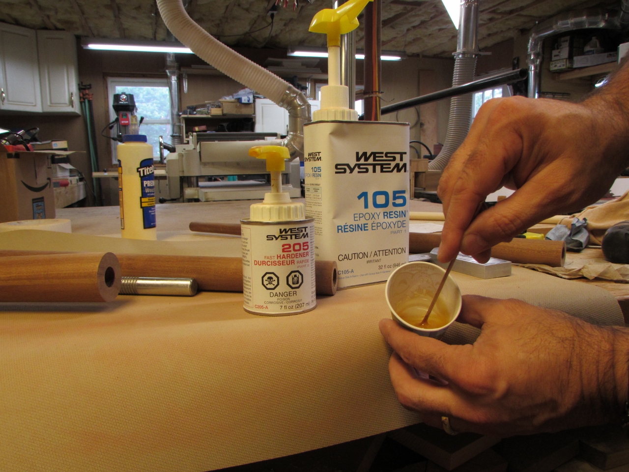
I used West Systems fast setting epoxy because it is very thin. It will squeeze into all of the threads more easily.
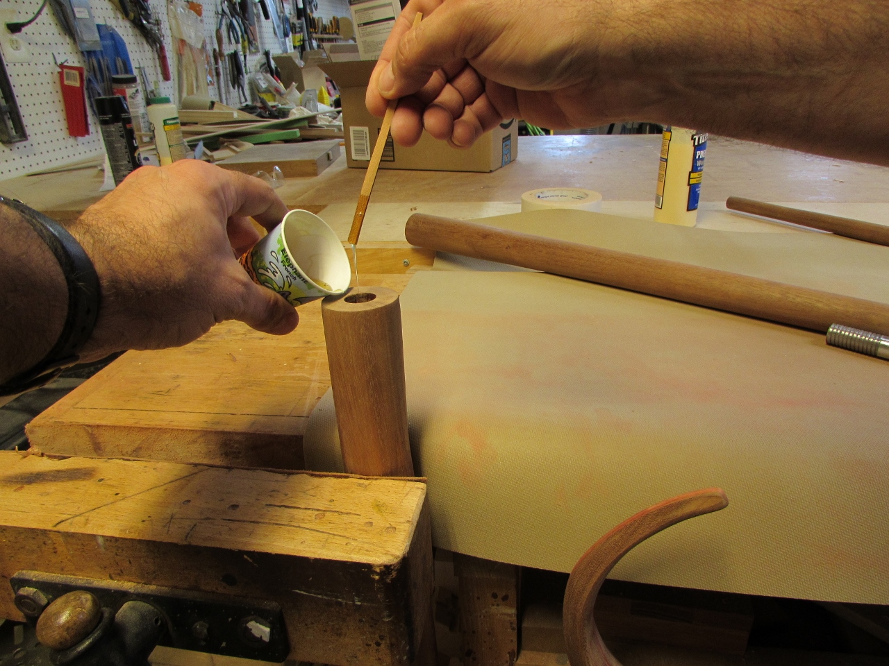
I lined the hole with the epoxy and twisted the post into it, taking my time to let air escape.
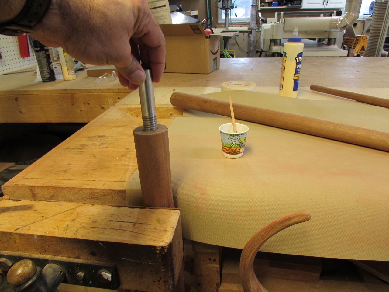
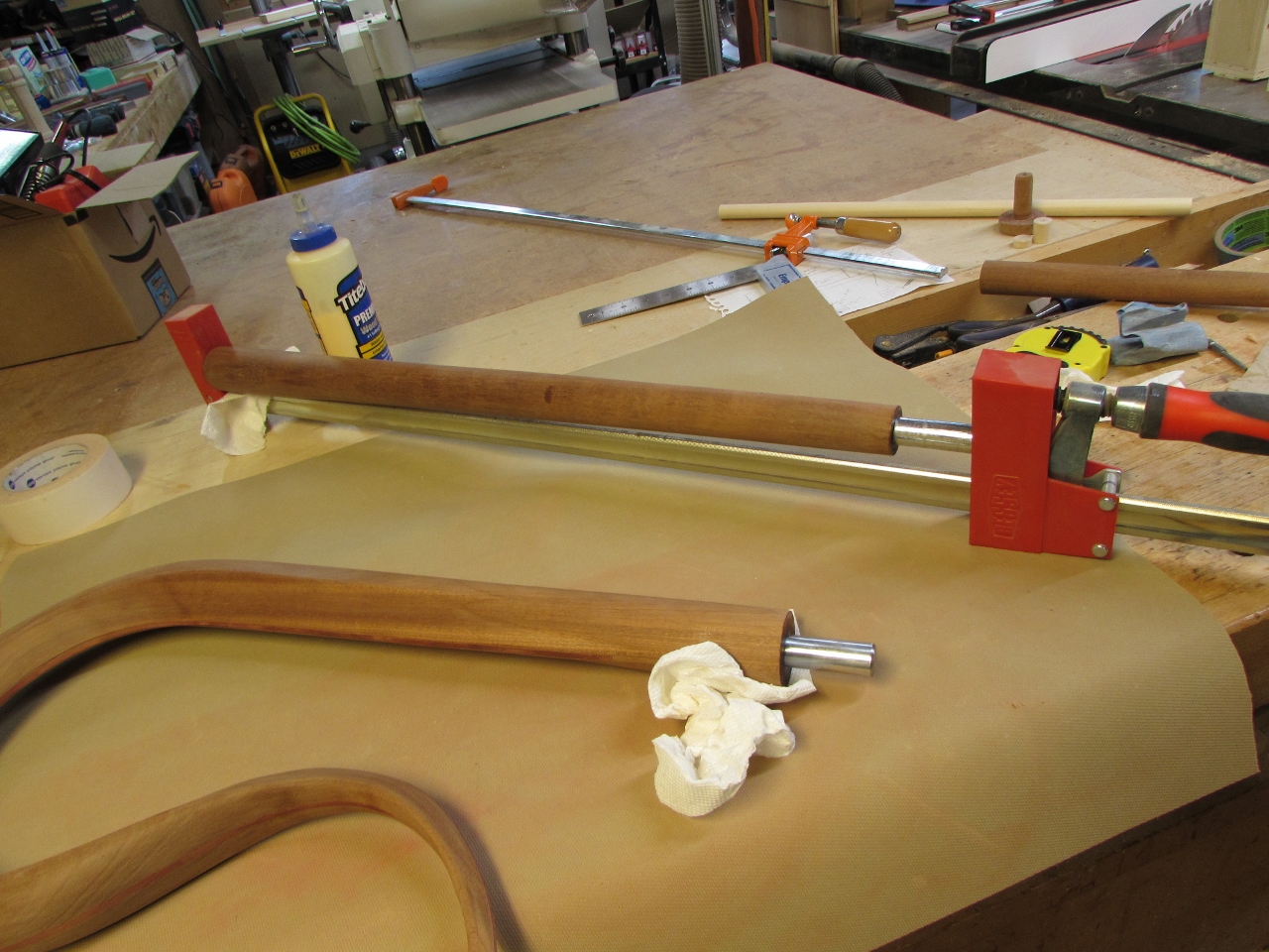
I had to use my big parallel clamps and my jig again, to hold the post in while it set up.
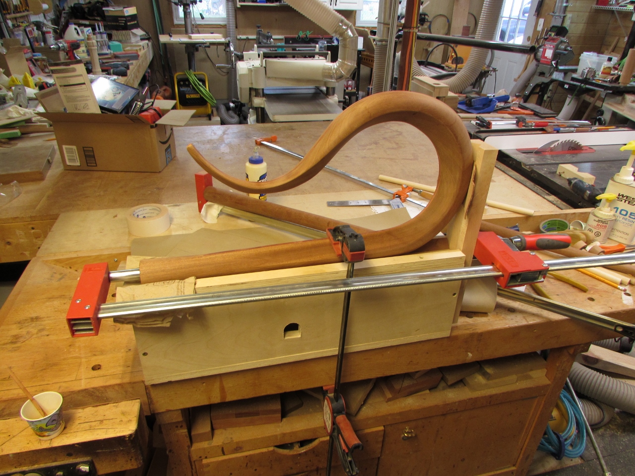
Amazingly, it all clamped up straight.
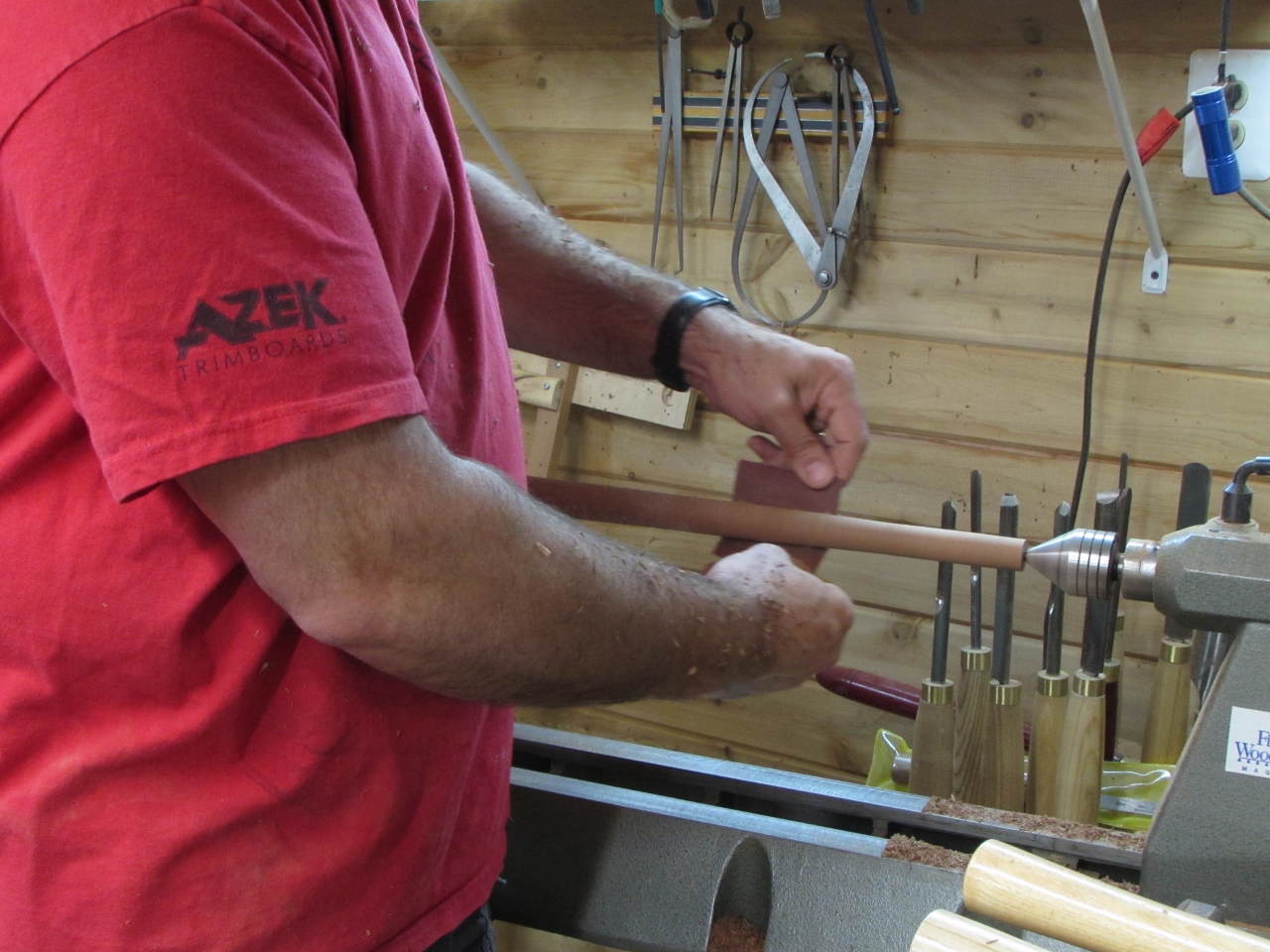
Just a bit more hand sanding and it is ready for finish.
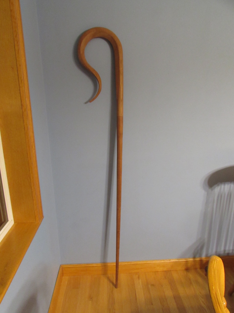
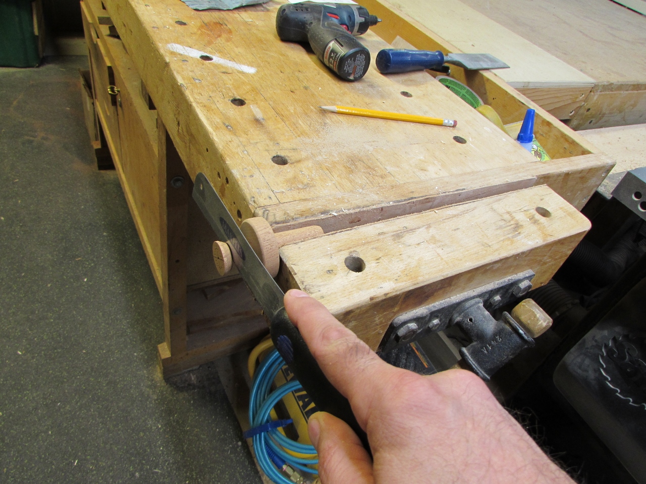
I will be handing this back to my buddy Dave now to apply the finish and hand it over to its new owner. He promised me some pictures so I will add them when I get them. I did make a neat little video showing how tight the connectors fit. Turn up your volume and hear the “pop”.
This was a fun project with lots of new challenges. I have a few more revisions that I will make if I have to do one of these again, but I am definitely happy with how this one turned out.