
Making a Bishop’s crosier
This project was an interesting challenge. My friend Dave was making a crosier for a bishop friend of his and he was running into some problems. He has a CNC of his own that costs a lot more than mine and it is a very capable machine, but the one thing that mine does very well is double-sided carving, and he is still learning the capabilities of his.
Dave’s CNC is a flat bed CNC, so you have to clamp down the wood you are carving. This makes it a bit difficult to re-align when you flip it over to carve the back. I think he managed to that part well, but suspects he ran into problems on the software side.
Basically his carve was shifted, about 1/2″ from one side to the other. A carve like this takes several hours to do, so it is not something you keep redoing until you get it right. You could waste days and a lot of expensive wood.
Dave’s first thought was to re-saw the board and glue it back together, but re-sawing wide stock is hard enough, but even harder with a non-rectangular shape.
After several hours of frustration and wasting a big chunk of Sapele, he set the project aside.
After a few months went by, he asked me if I would make an attempt at it.
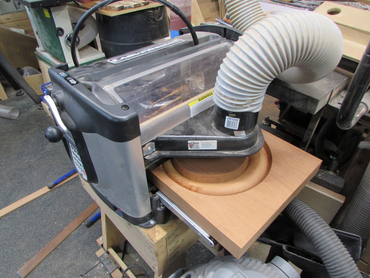
My Carvewright CNC is more of a hobby CNC than an industrial workhorse. It feeds the wood back and forth on a rolling bed, instead of having the router moving over top of a fixed piece of work. One of the benefits of this is that I can put a 12′ long piece of wood through it, and carve the entire thing as long as I have room for the outfeed. I just can’t do anything wider than 14″. The way that it feeds things also requires it to have sensors to track the edges of the board. This enables me to have some fairly accurate double-sided carves.
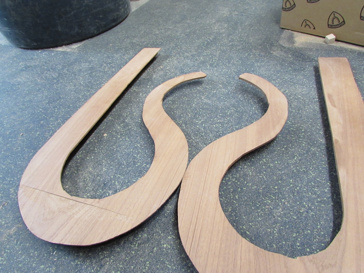
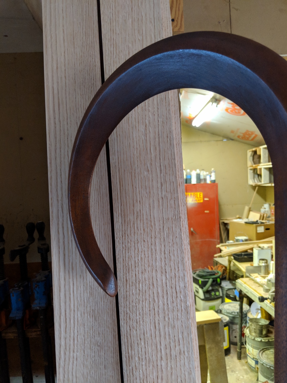
I tried to mimic Dave’s design as well as I could, but his piece of Sapele had some wonderful cross grain at all the right places, my piece was really straight grained and I worried that it would make the re-curved piece at the end rather weak.
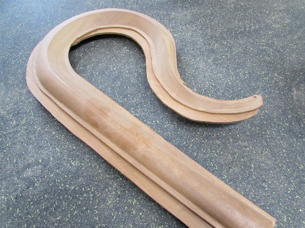
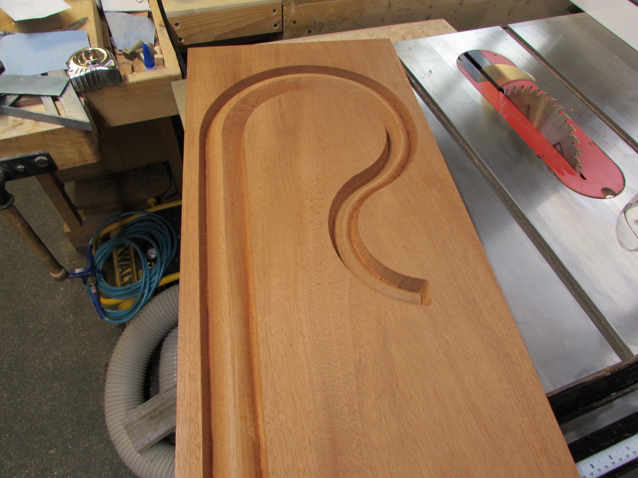
My carve took about 4 hours on each side, and left a very thin wall between the two sides. I used a utility knife to finish cutting through and I had the top of the crosier.
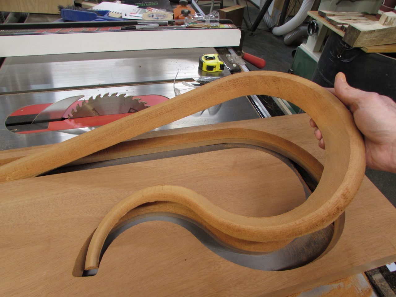
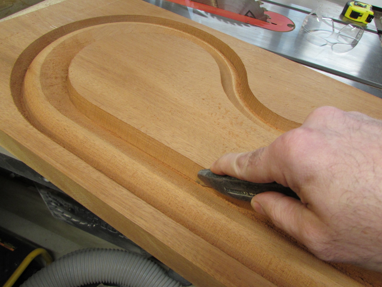
The carve is always rough in some places where the cutter goes against the grain, so I spent some time doing some rough clean-up.
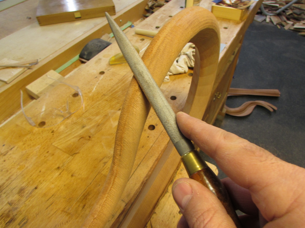
My double-sided carve only shifted a bit, less than 1/32″. That is perfectly useable, just a bit more sanding to take care of it.
The next challenge was figuring out the connections between the sections of the staff. I have never looked at one close up before, but Dave tells me that they have to be broken down, typically to three or four pieces, so they can be transported easily. The usual method of connection is the same hardware that is used on pool cues. After doing some research on pool cue joint hardware, I started looking for a different option. It looked like I would have to invest in installation tools that I would never use again, and it seemed like it would need a lot of precision to get it right.
I thought about it a bit and decided to play with magnets. It seemed like a pain to screw together all the sections and pool cue hardware is not the strongest if it gets stress on the joint. I had a few 3/4″ diameter, 25 pound pull magnets, that I thought would work perfectly. My first concept was a tapered connection with a magnet at the bottom of the socket and a steel washer at the tip of the male end. I made a proto-type that worked perfectly. Check out the short video below.
Unfortunately I have no way of accurately drilling the tapered socket without a large, open chuck to feed the staff sections into, so I can drill it dead centered. I would need a machinist’s lathe, and I do not have one. These small sections can be held in my chuck without a problem, but the 30″ long staff sections would just whip around. So, prototype #1 got scrapped.
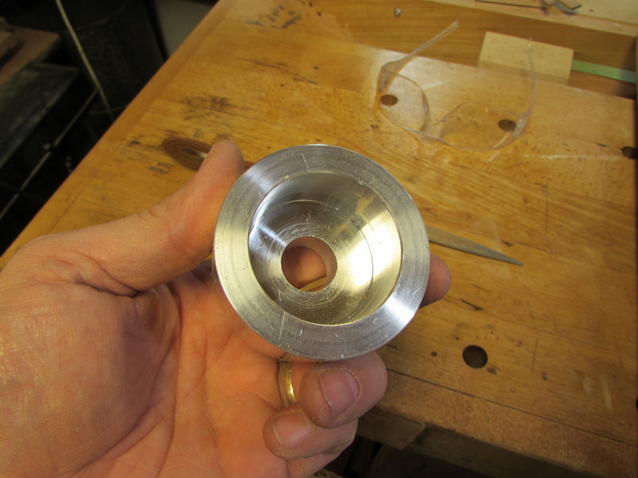
My next option was to try a round, steel bar that could be epoxied into one section and a hole drilled into the opposite section with a magnet located at the bottom of the socket. To do this, I had a friend make me a drill alignment jig out of aluminum.
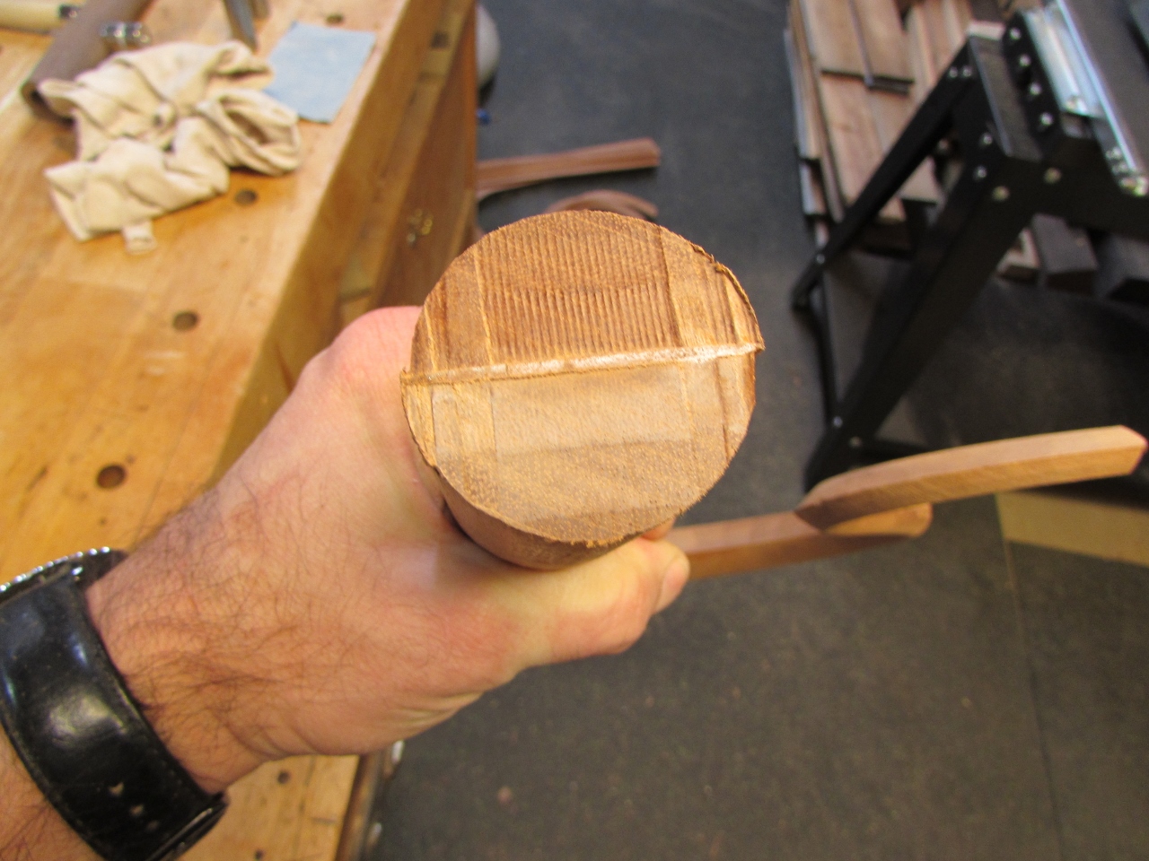
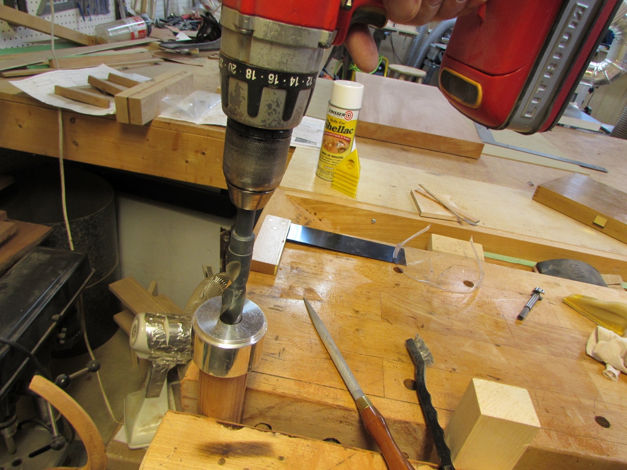
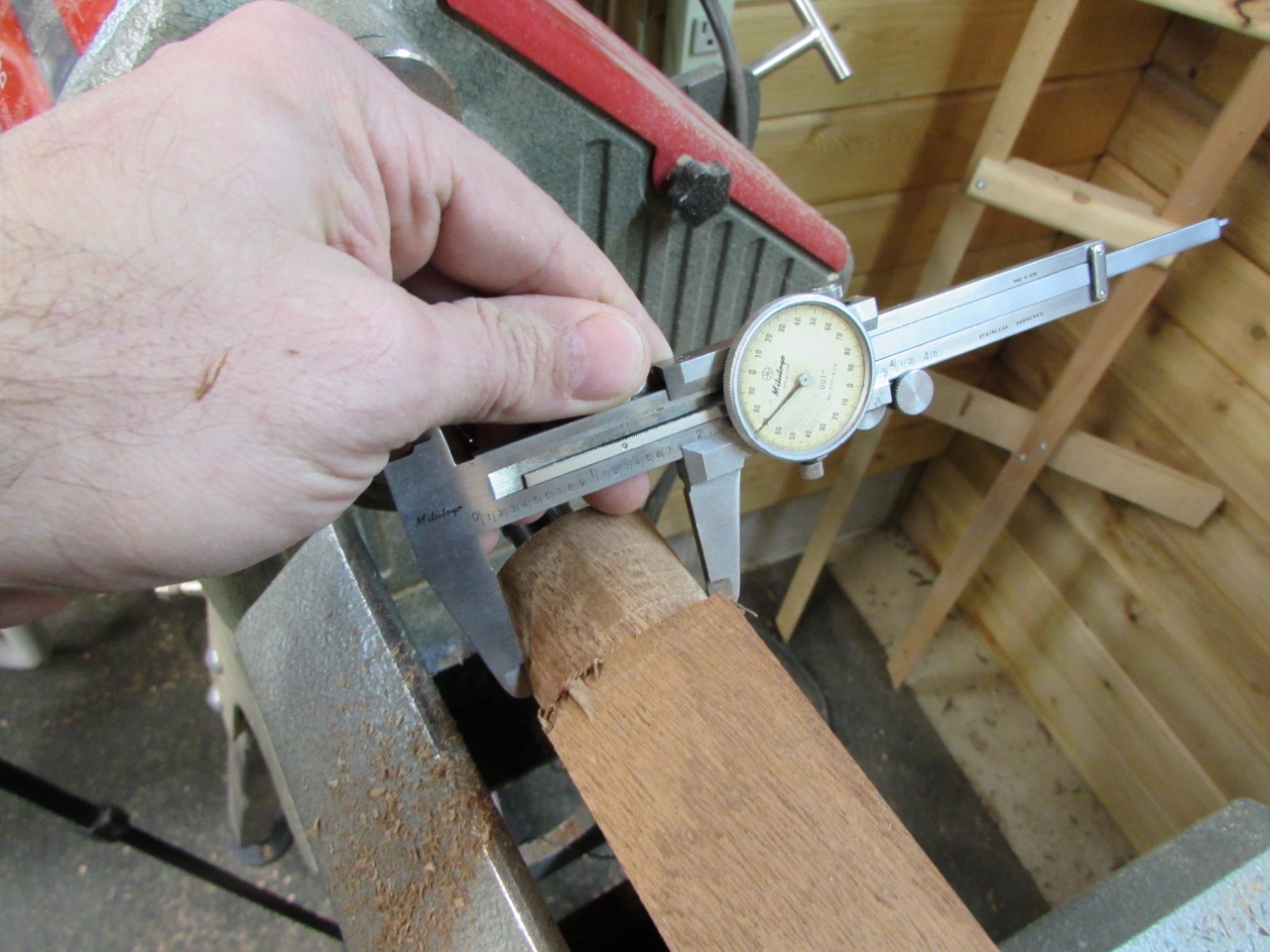
To test it out, I cleaned up the end of the head piece and checked it for square.
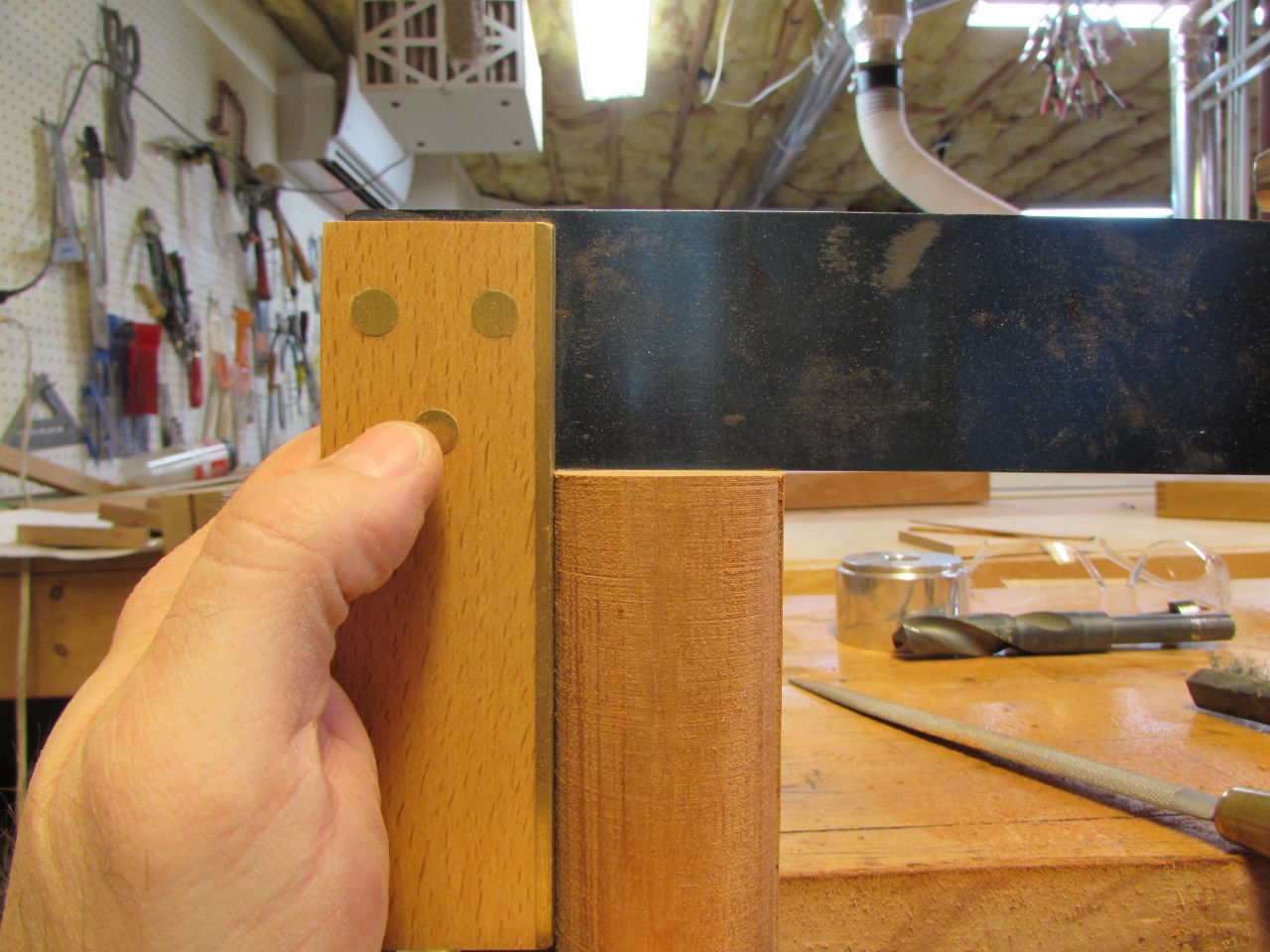

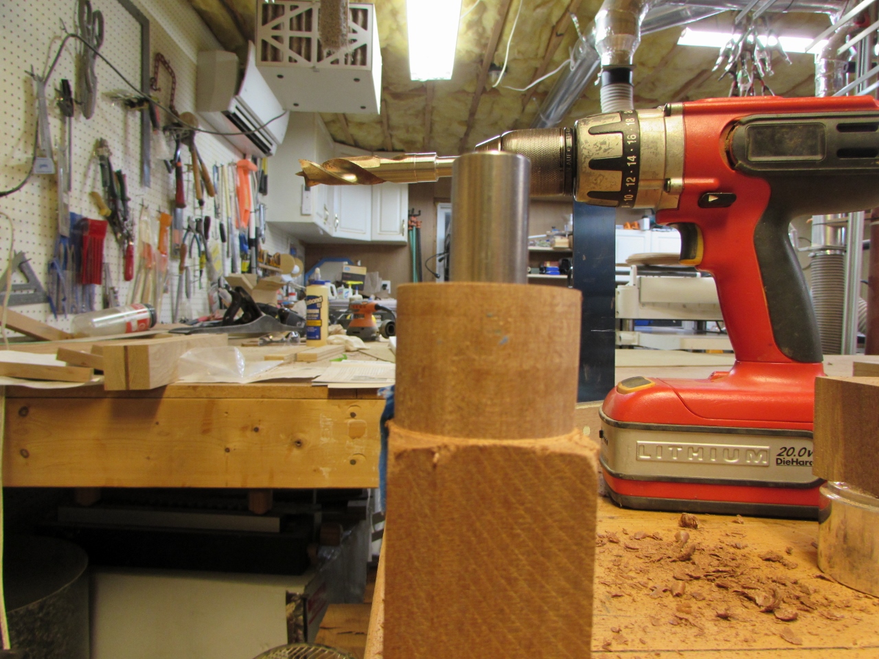
I placed my alignment jig in place and started with a forstner bit, but quickly realized that the smaller shaft would not stay in line after the cutter cleared the aluminum.
I then tried it with both a twist drill bit and a brad-point bit.
Both were far too aggressive and wound up chewing up the aluminum opening. My hole also was slightly askew. That will be a problem, but I may be able to compensate for it later. I had a friend cut me some 2″ long sections of 3/4″ steel rod. My intent is to epoxy them in place and have at least 1″ of engagement on each side. Hopefully that will be enough to prevent wiggle.
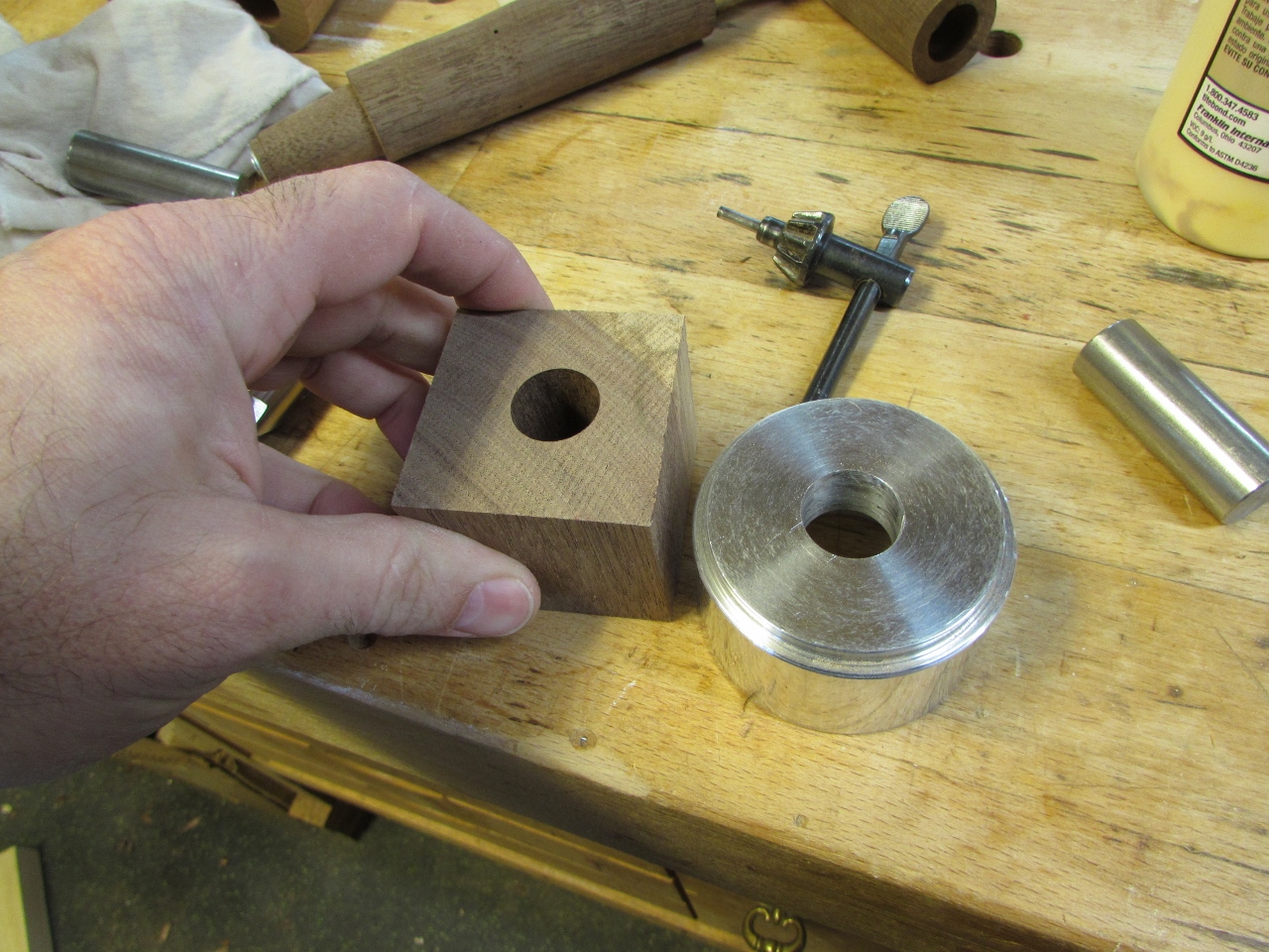
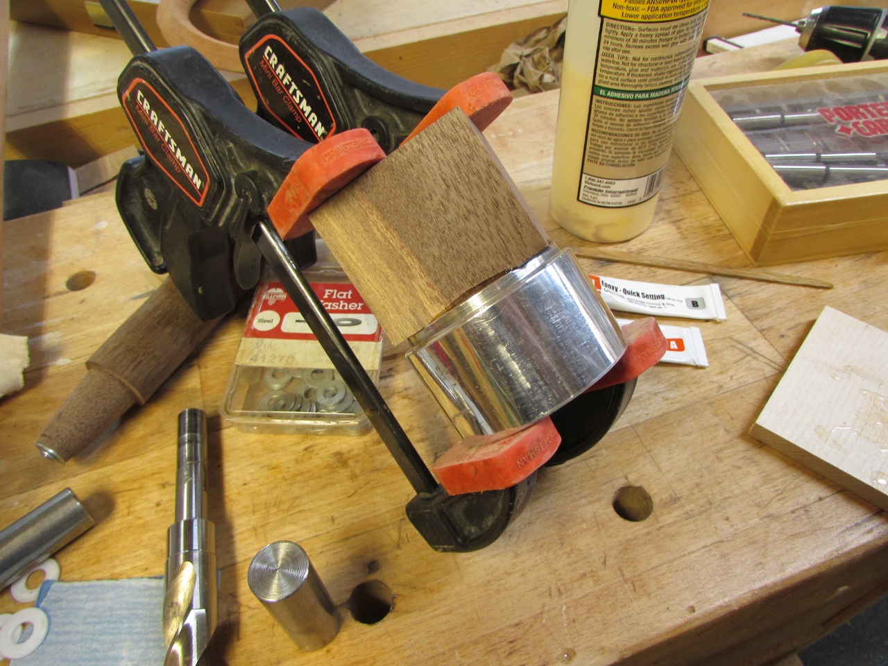
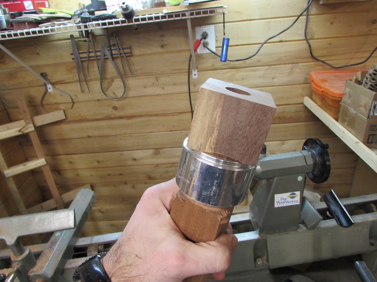
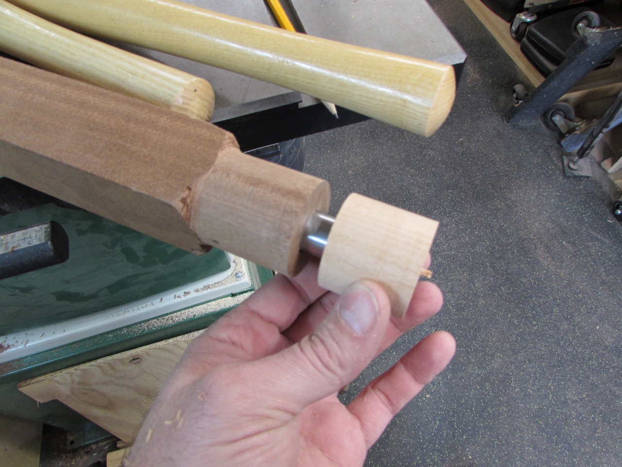
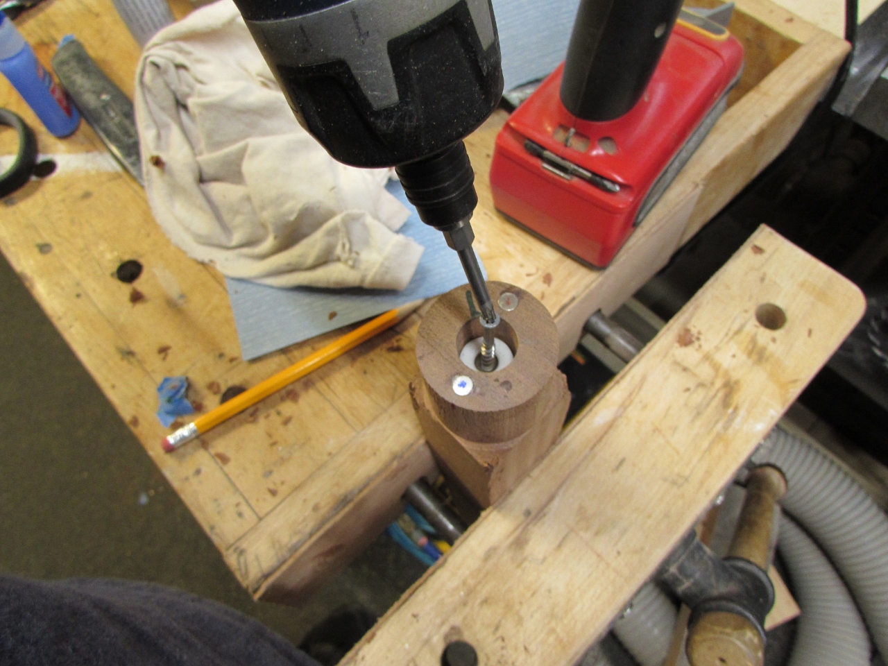
Obviously the 3/4″ section of my jig needs to be several inches longer… I cut a 2″ cube of walnut and drilled a 3/4″ hole through it, on the drill press.
I placed a steel shaft in the hole and used it as an alignment pin as I epoxied the block in place.

Once seated, I clamped it up and removed the pin so it wouldn’t get epoxied in place.
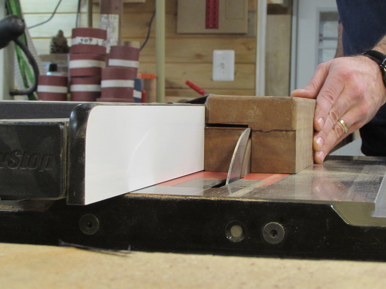
Next I cut some 1-3/4″ square pieces to become the other two sections of the staff.

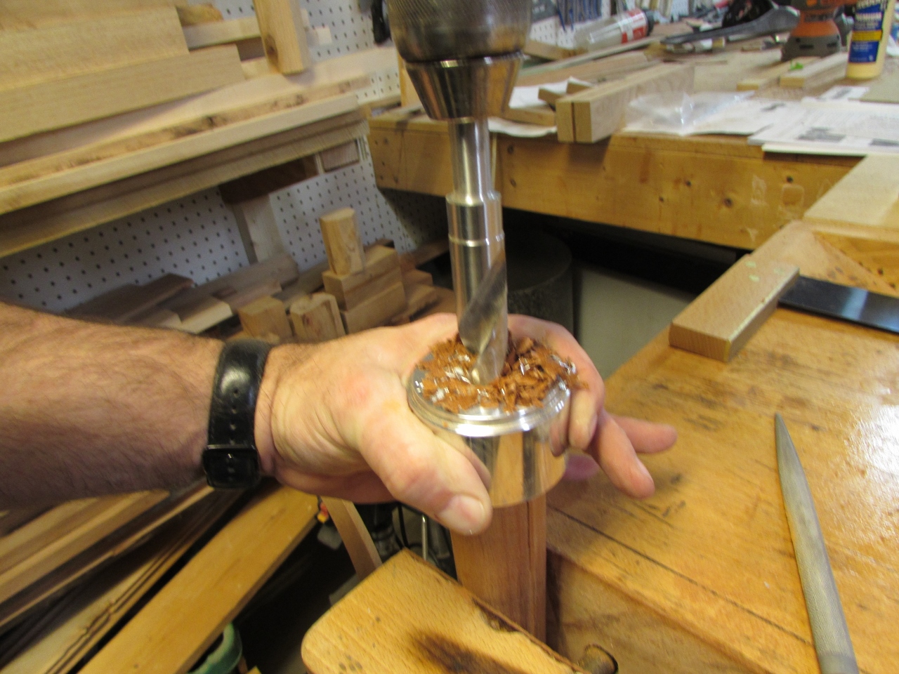
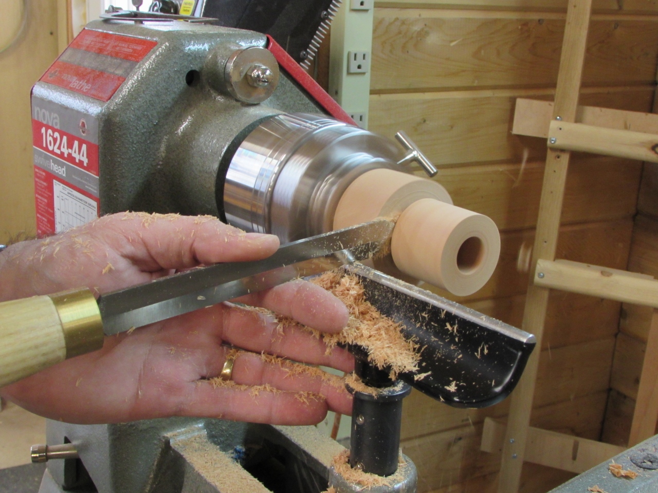
Remember, at this point, I am making this all up as I go along. I am sure there are better ways of doing this, but you have to start somewhere. I centered each leg section on the lathe, and cut a 1-3/4″ section on each end.
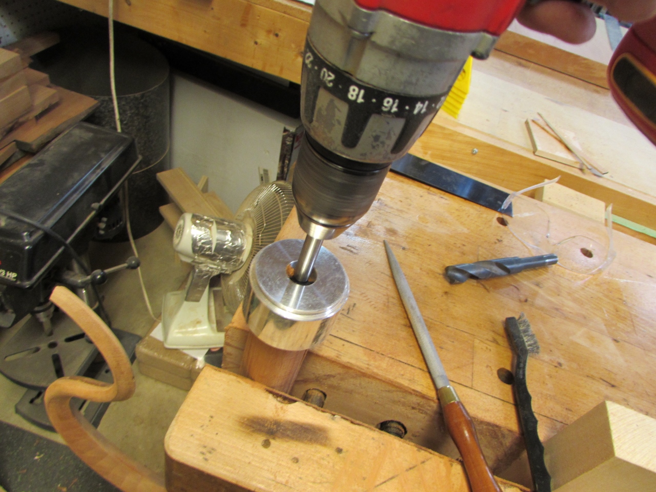
This allows me to center my drill jig onto each end, for drilling.

Again, the bit was very aggressive, but it did work better.
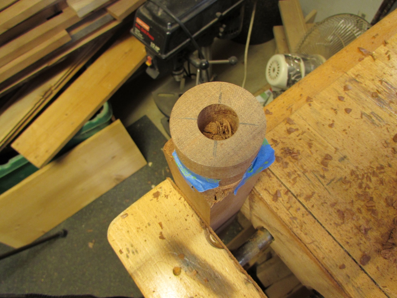
It did drill a much more centered hole, but still not perfect.

I placed the steel pins in place to test the connection.

Not too bad really.
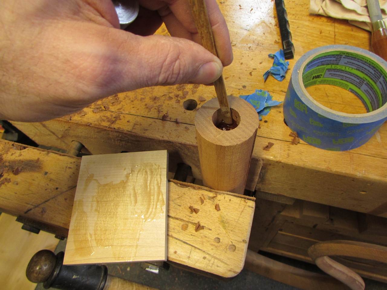
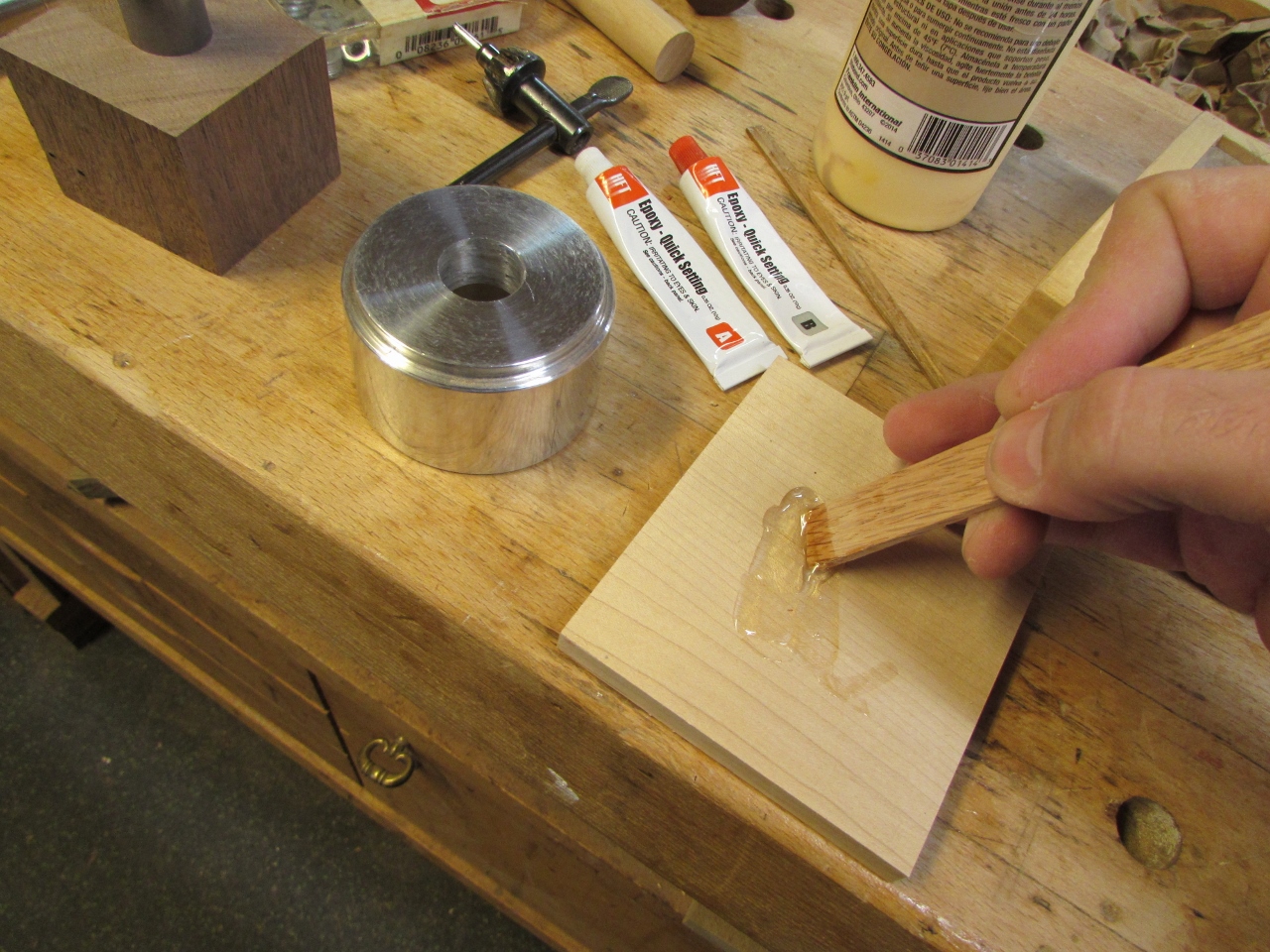
I mixed some epoxy and set the pins in place.
To try and keep them perfectly aligned, I taped off the socket side (to prevent the epoxy from sticking to the female side) and connected the sections together. I am using a quick-set epoxy, so I only needed to hold it in place for about five minutes.
Once everything had cured, I fit them back together. When the grain was aligned, it was a perfect fit, but when I rotated one side 180 degrees, you could tell that it was not perfectly drilled. I spoke to Dave about this, and he said to proceed anyway, he has a plan to place the finished sections into a friend’s metal lathe and drill the hole larger, then set a brass tube in the hole creating a perfectly perpendicular socket that will not wear out as quickly.
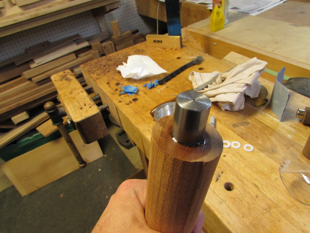
I forgot to take pictures of the magnets being installed, sorry. Nothing to it really, I set the magnet on the end of the metal stud, then measured the total length, then used my forstner bit to drill to the correct depth, and epoxied in the magnets.
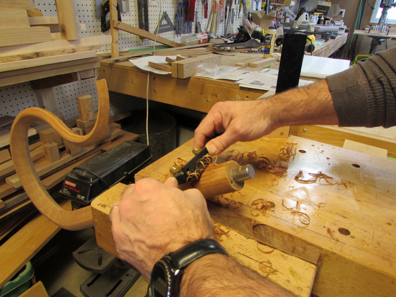
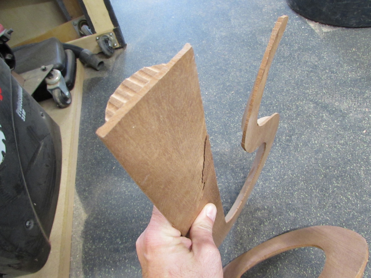
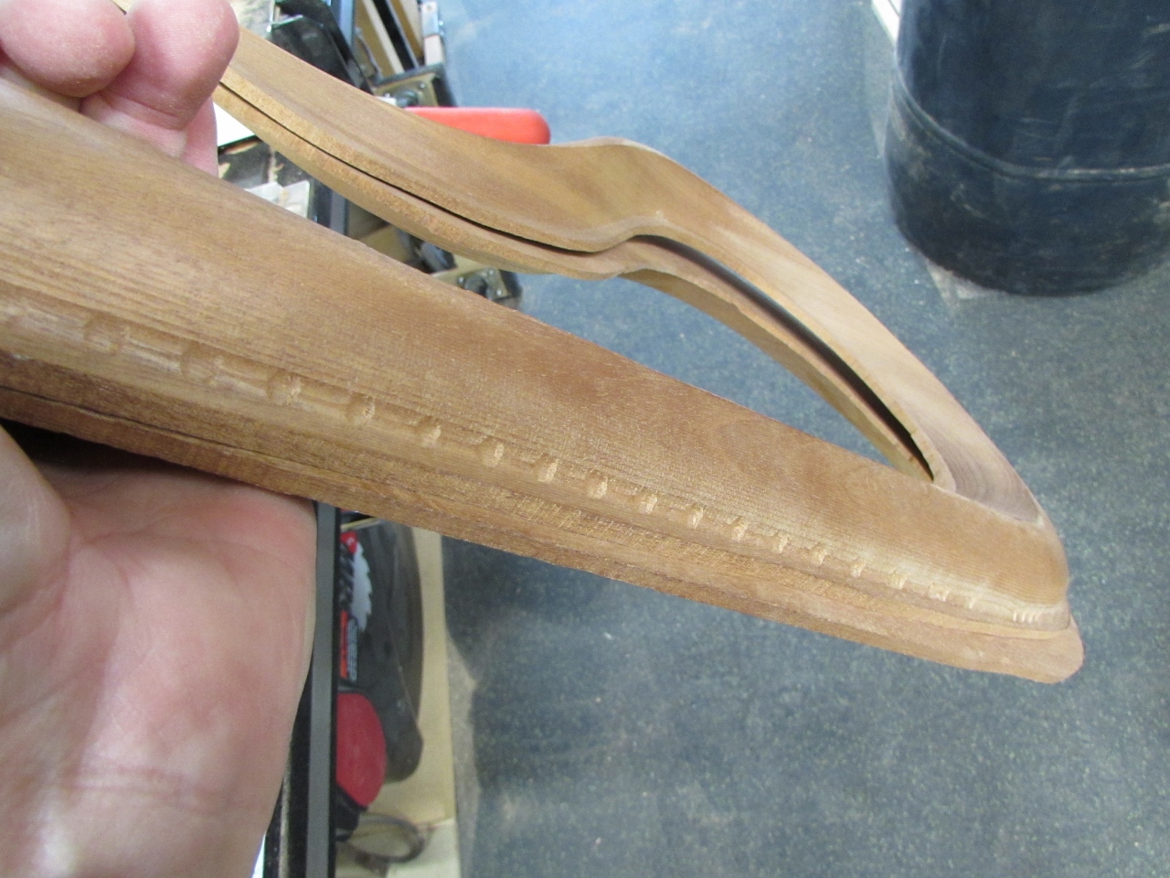
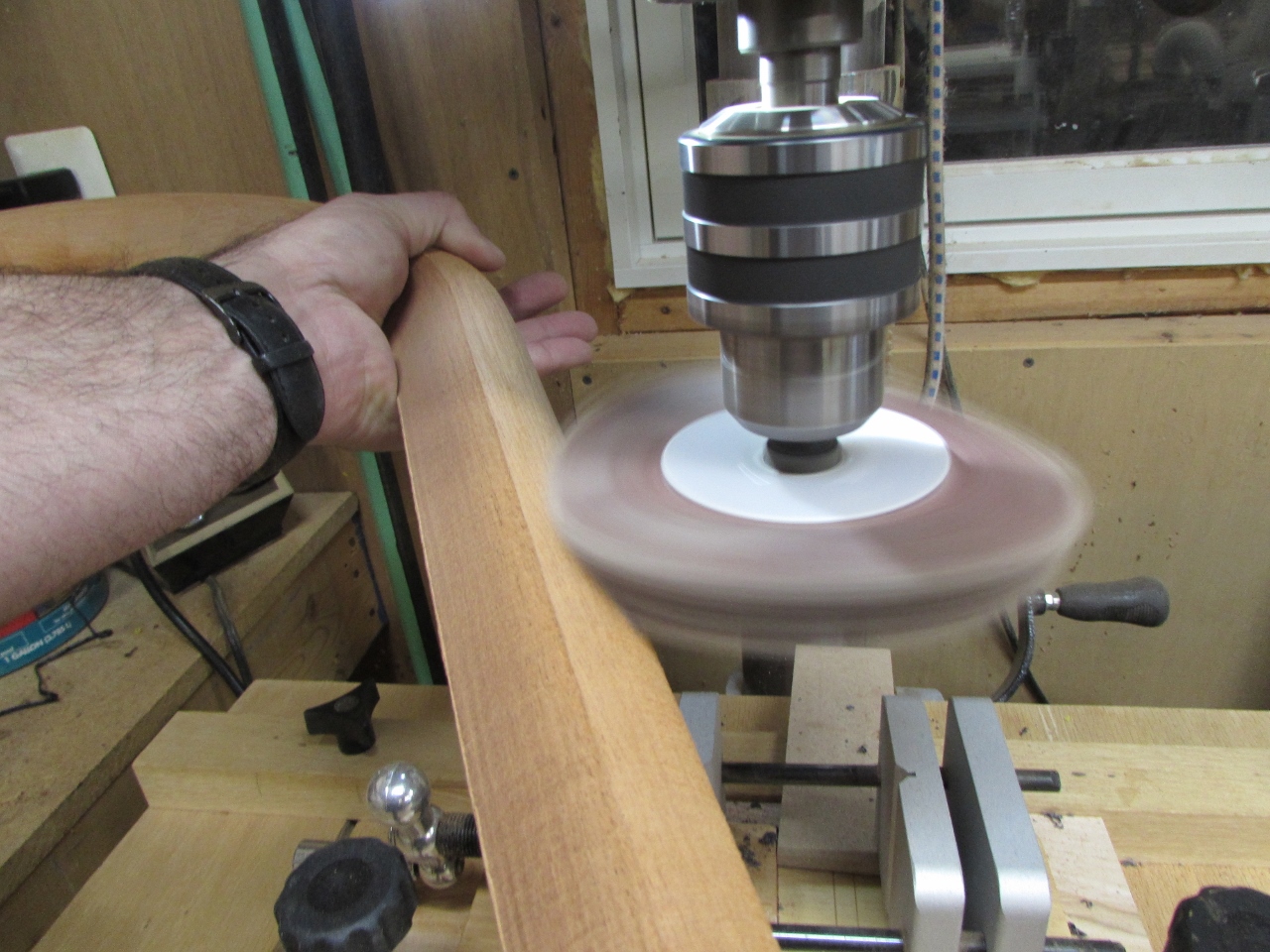
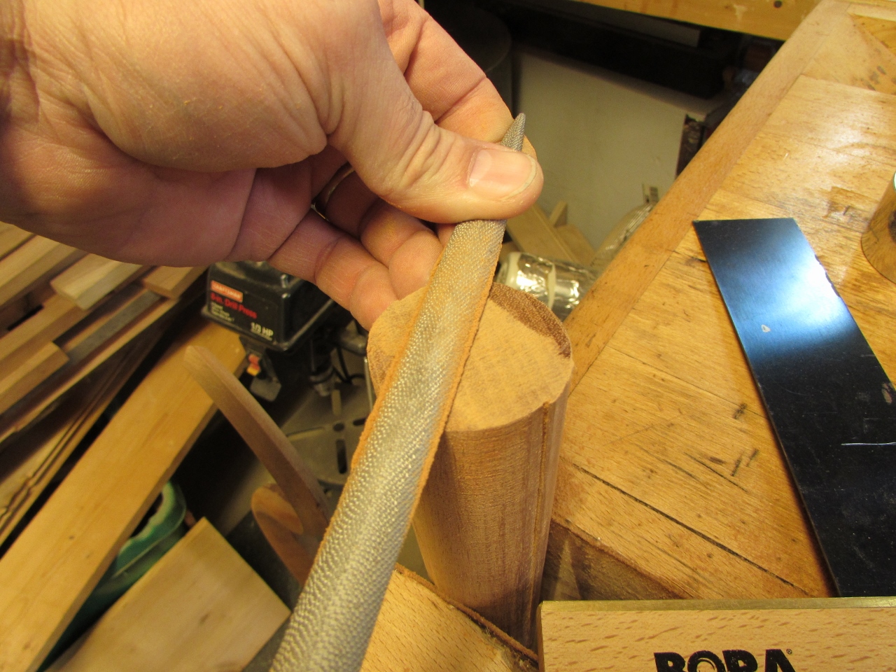
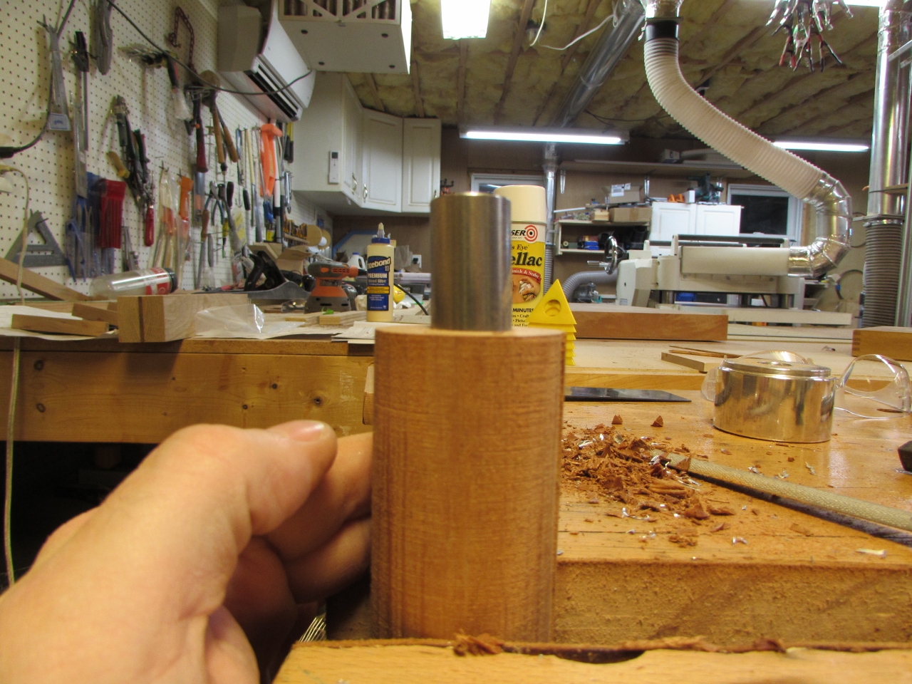
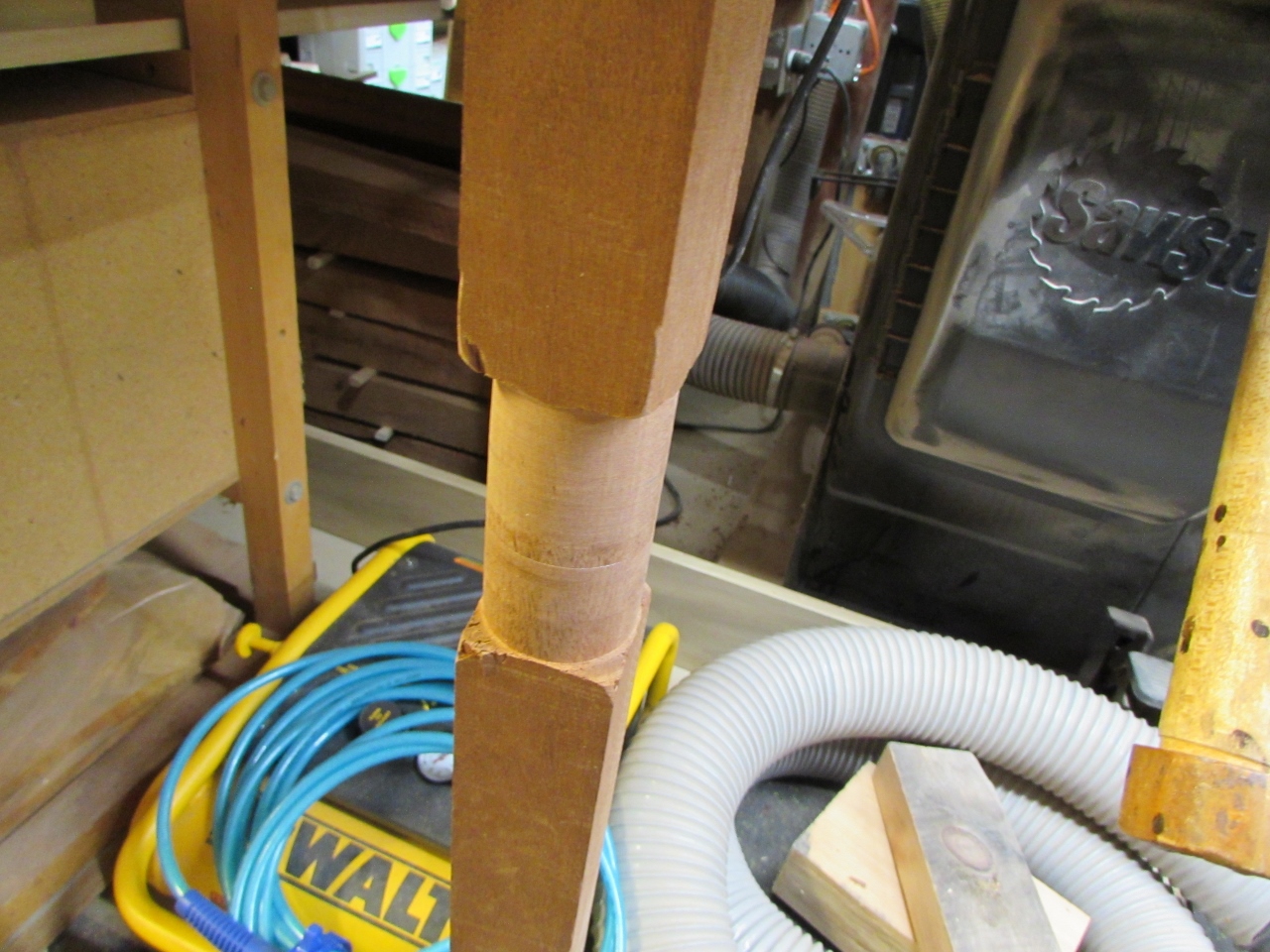
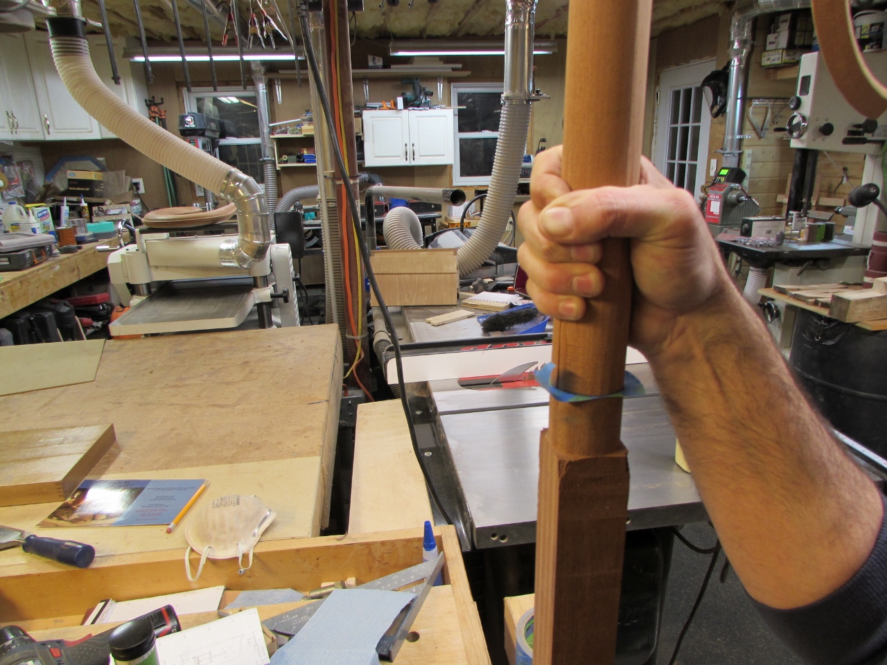
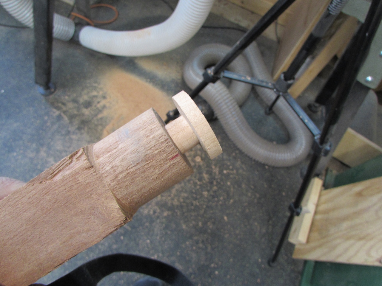
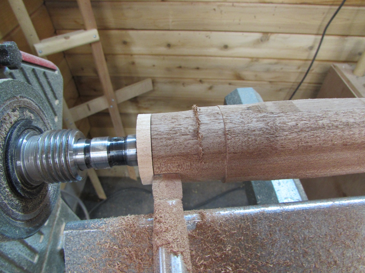
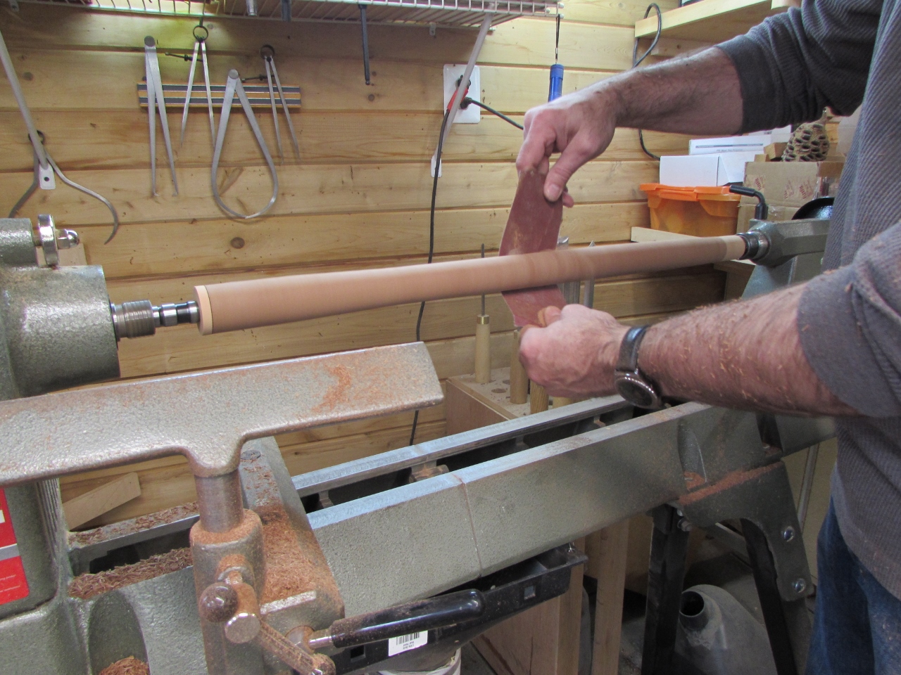
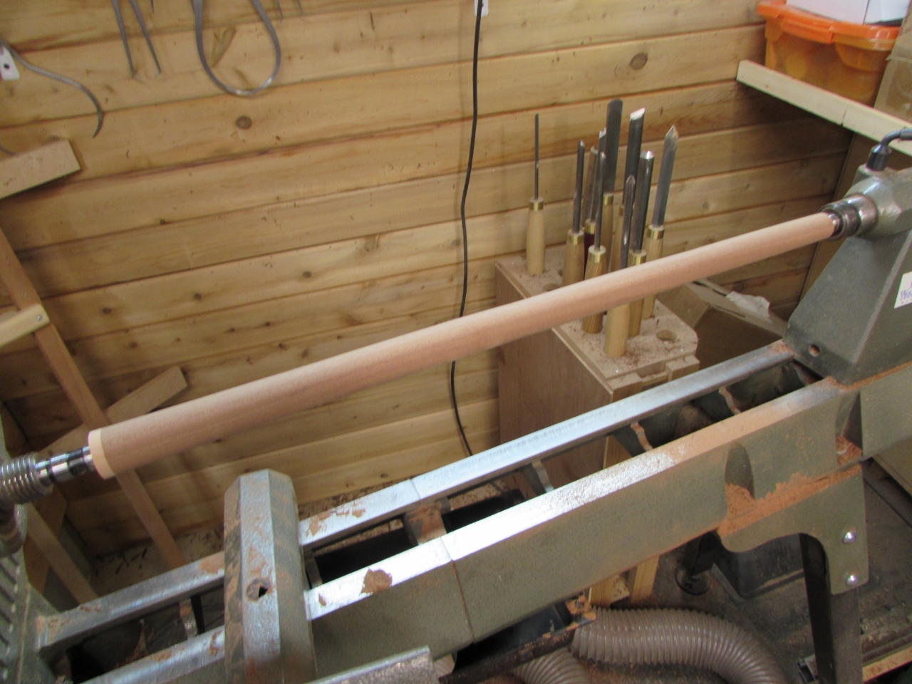
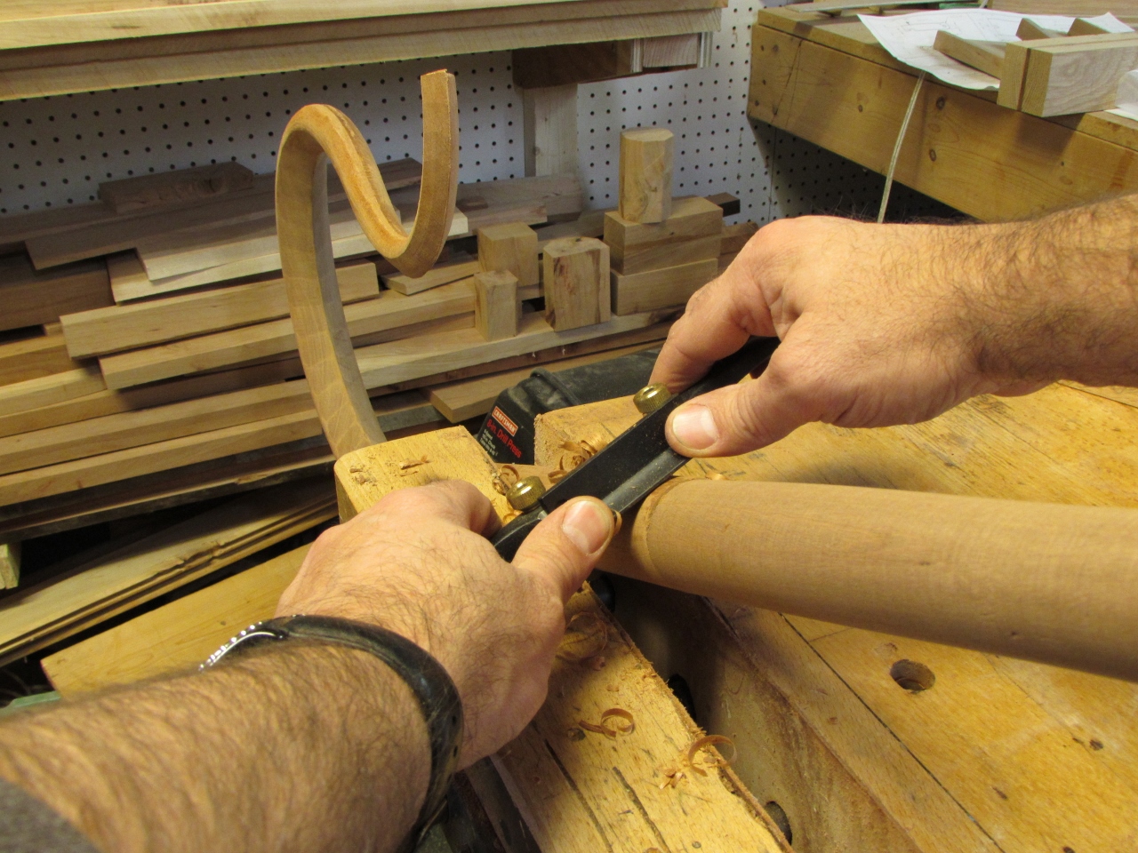
I took a break from the connections for a bit and spent some time cleaning up the end of the carved section, using a spoke-shave to take the connection end down to the 1-5/8″ diameter that I would be turning the thick end of the staff down to.
The staff will be taped down from 1-5/8″ to 3/4″ at the bottom. Since I started with 1-3/4″ at each end of the staff sections, then drilled and epoxied the pins in place, I now had to figure out how to hold the leg sections on the lathe and take them down to size. I immediately thought of how I used bushings to turn a pen.
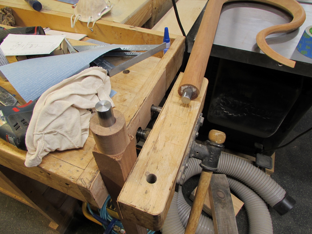
I made a bushing for 3 of the 4 ends. Both male and female, with the larger diameter sized to the final diameter of each end.
My staff will be 1-5/8″ at the top and 3/4″ at the bottom. The staff sections are 52″ long, so that makes the center section 1-3/16″. This gives me the dimensions that I need for my bushings.
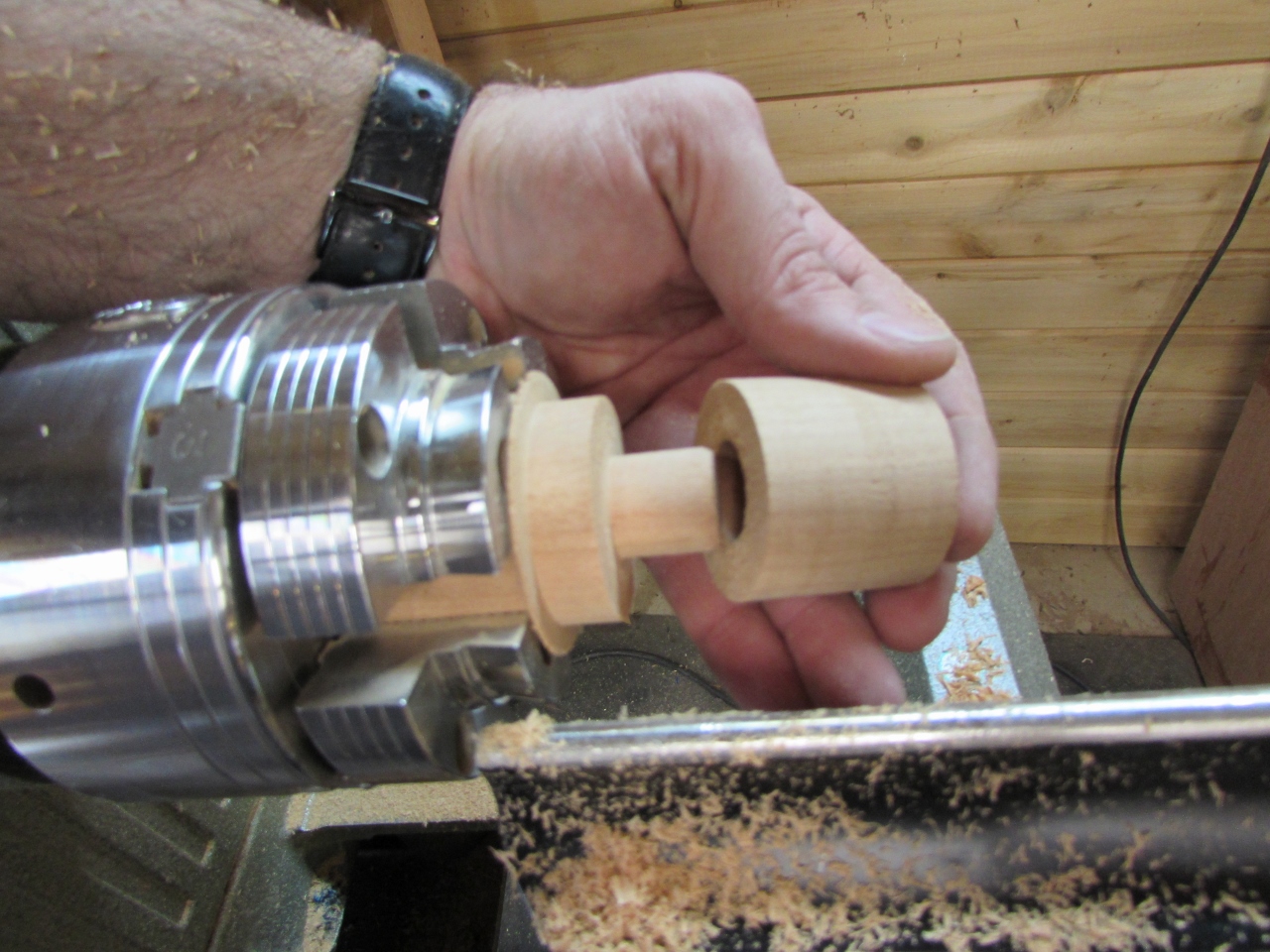
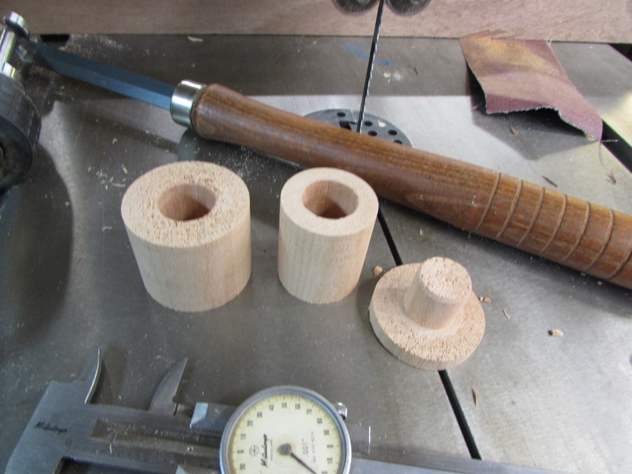
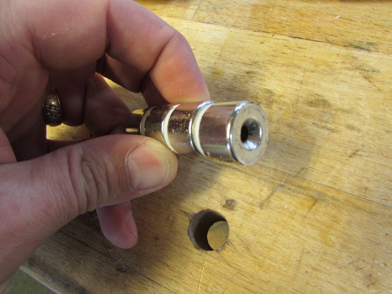
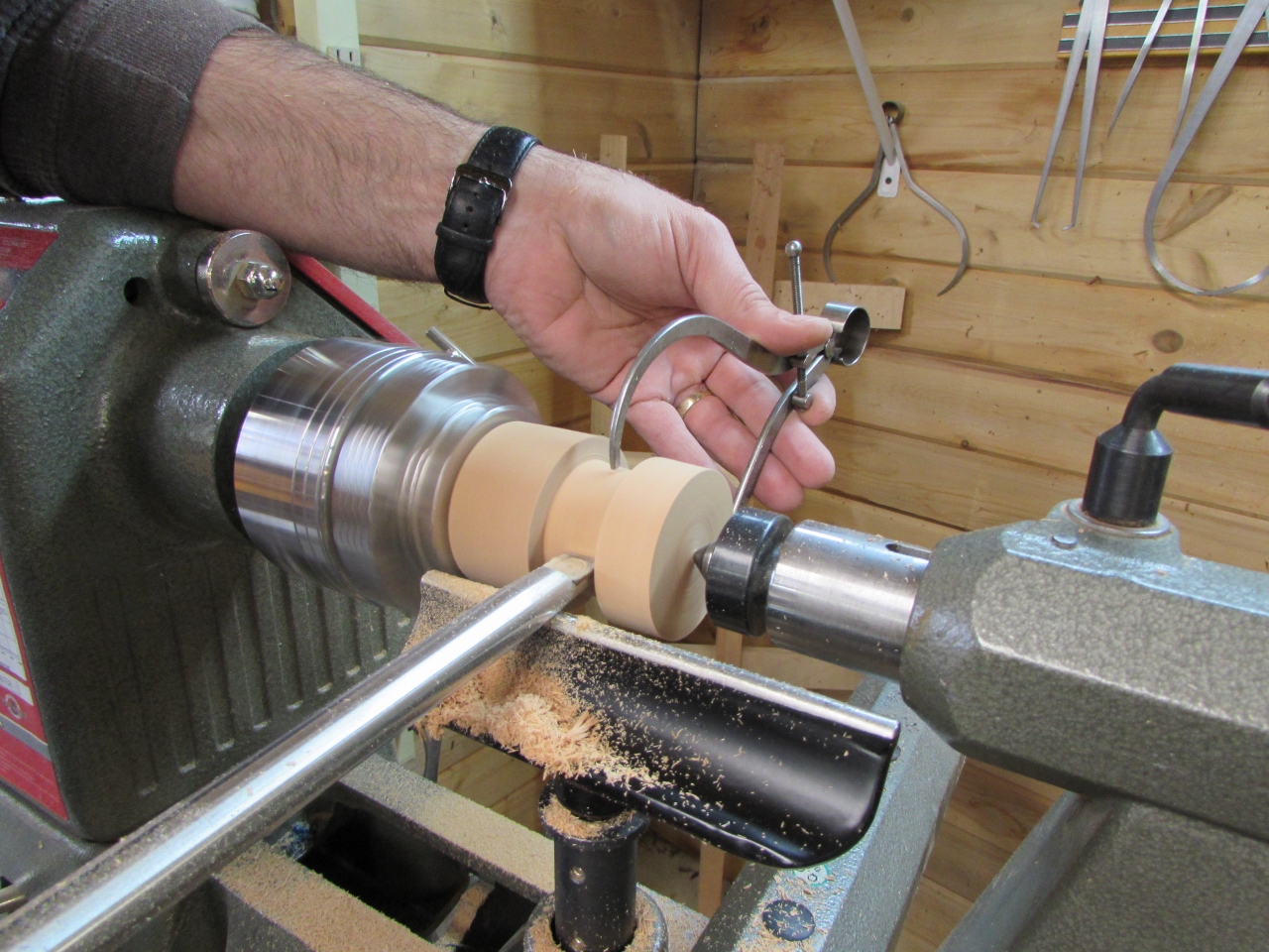
I wound up with a 1-5/8″ male bushing to set inside the hole at the top, and a 1-3/16″ female bushing to slip over the metal tip at the other end.
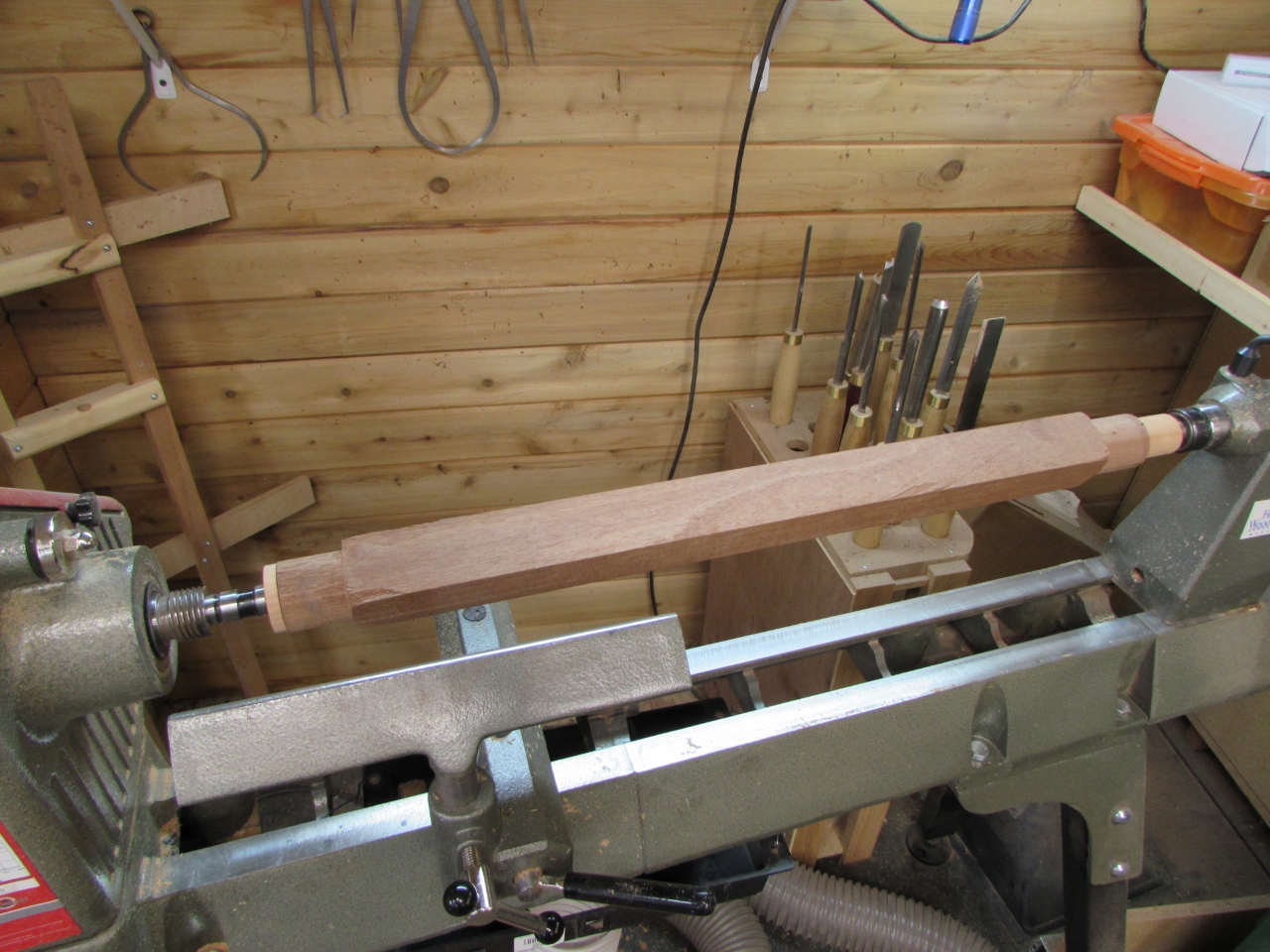
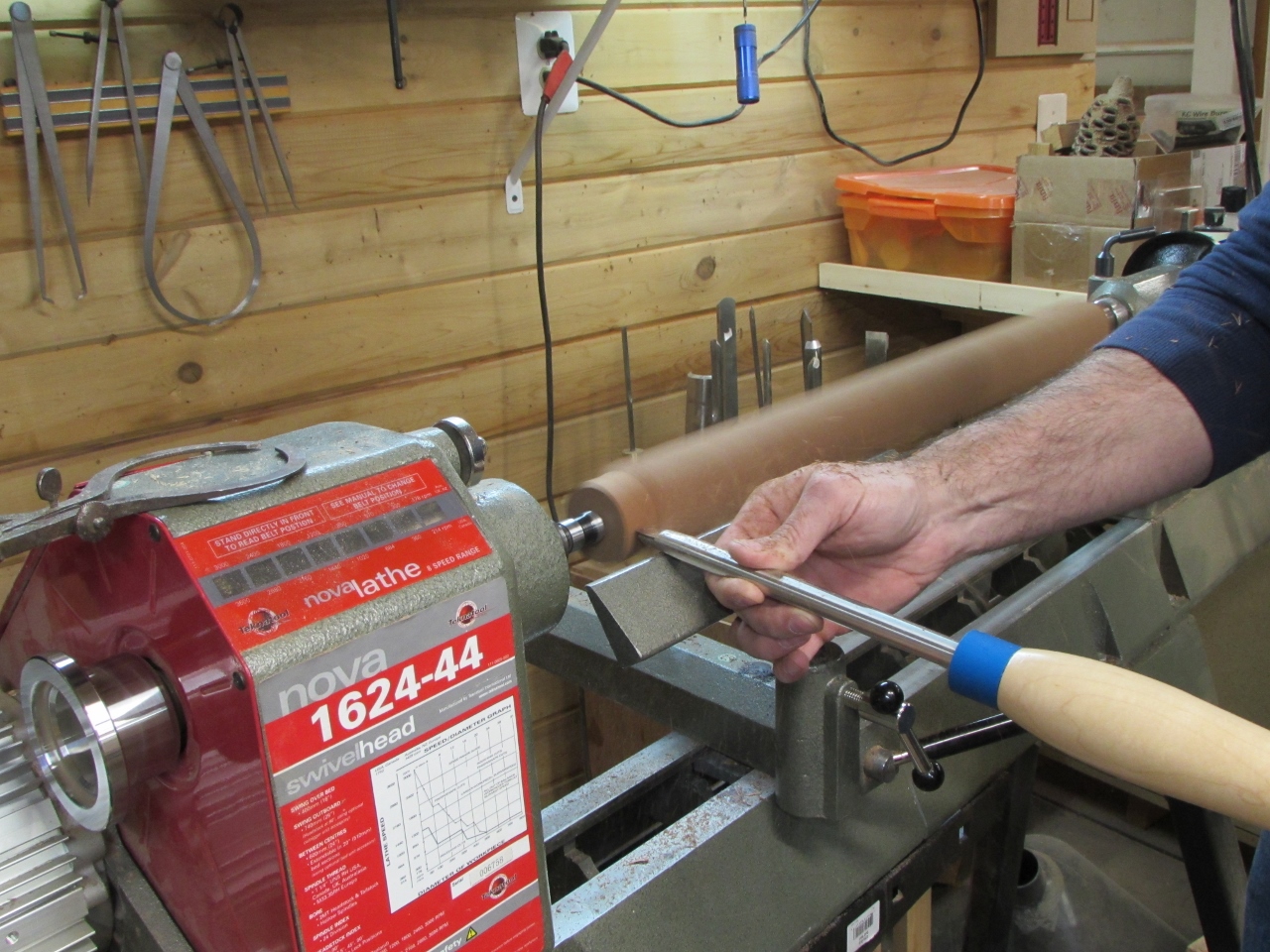
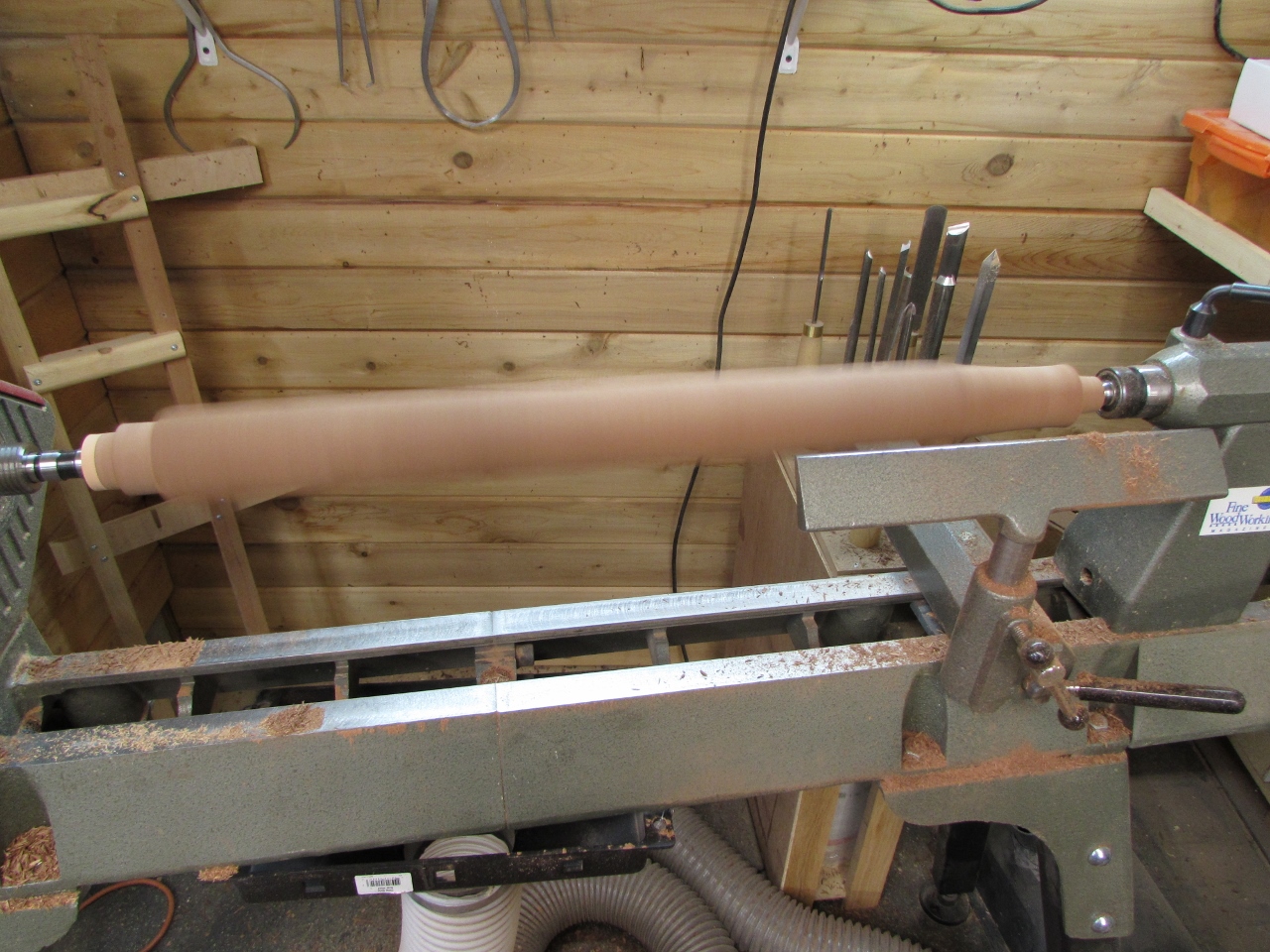
I cut the ends down to match the bushings, then cut down the rest of the taper in between.
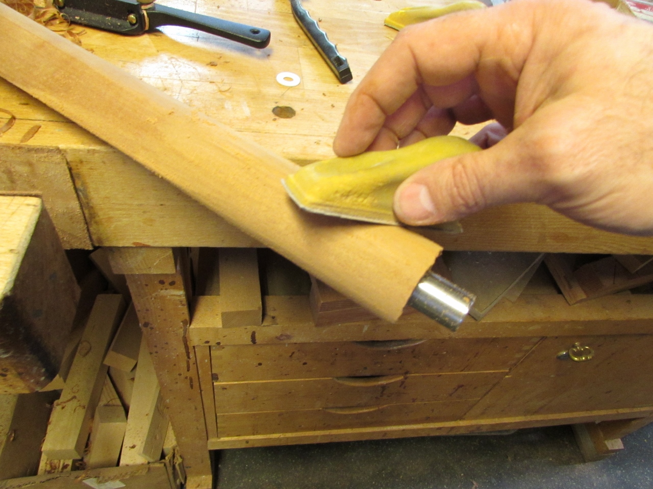
I rough sanded the shaft to remove the tool marks.
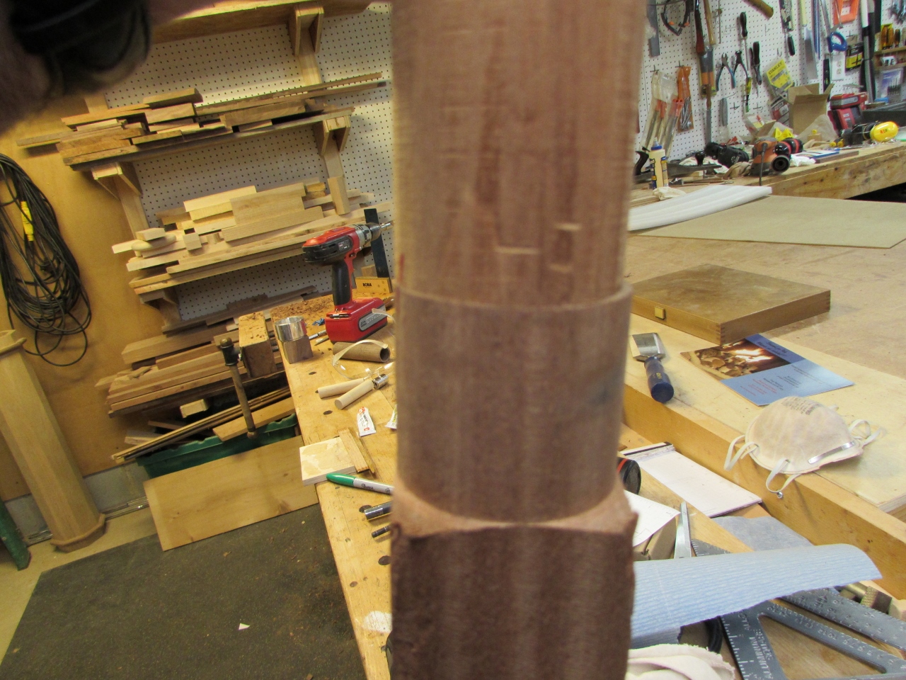
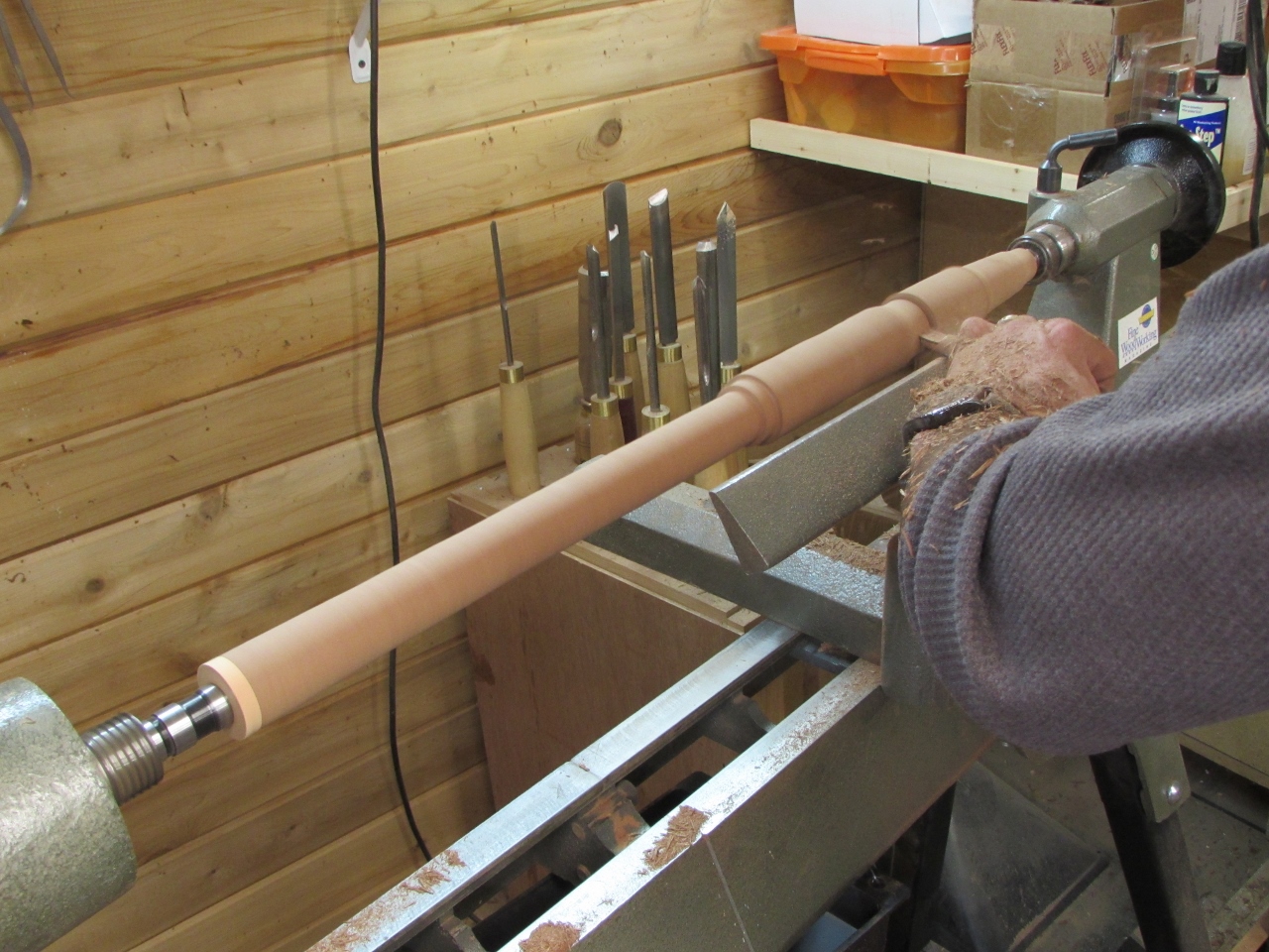
The first section blended pretty well to the top piece.
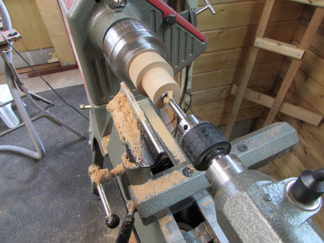
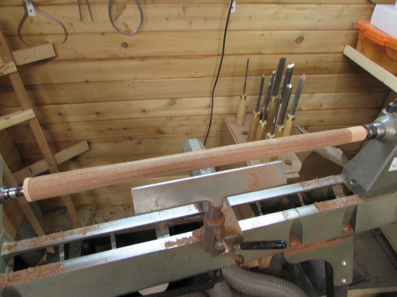
Then I inserted the 1-3/16″ male bushing into the end of the bottom staff piece and didn’t bother with a bushing on the other end. The very bottom was cut down to 3/4″ and the hole left in the end from the live center, in the tail stock will be the location for us to screw on a rubber or metal tip when it is all done.
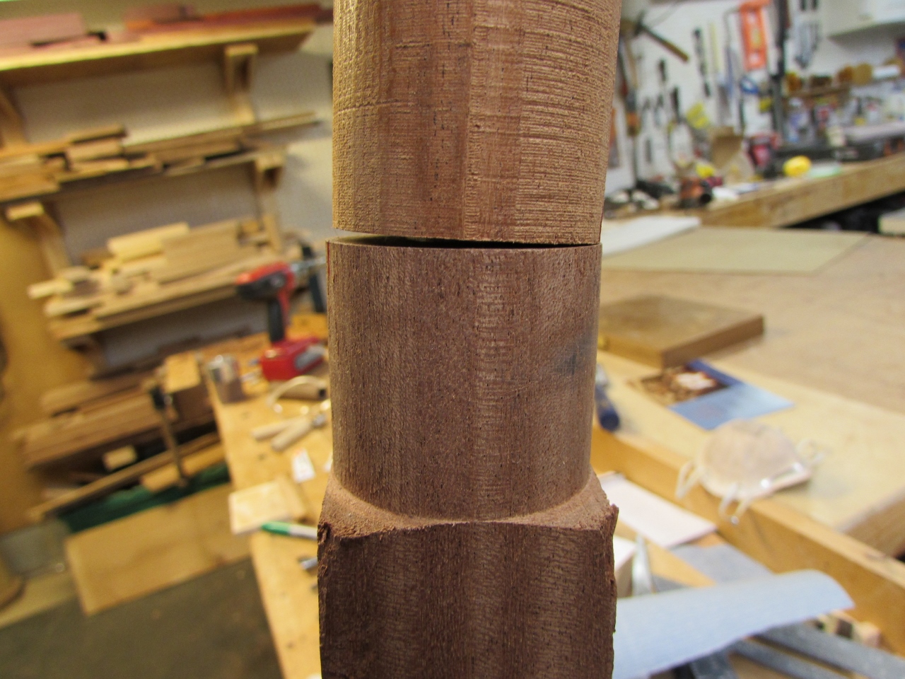
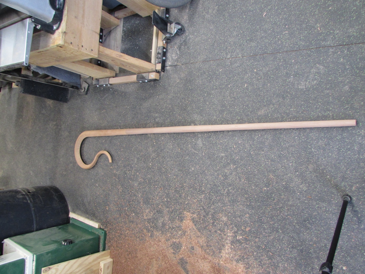
Then all that was left to do was to cut down the taper and sand.
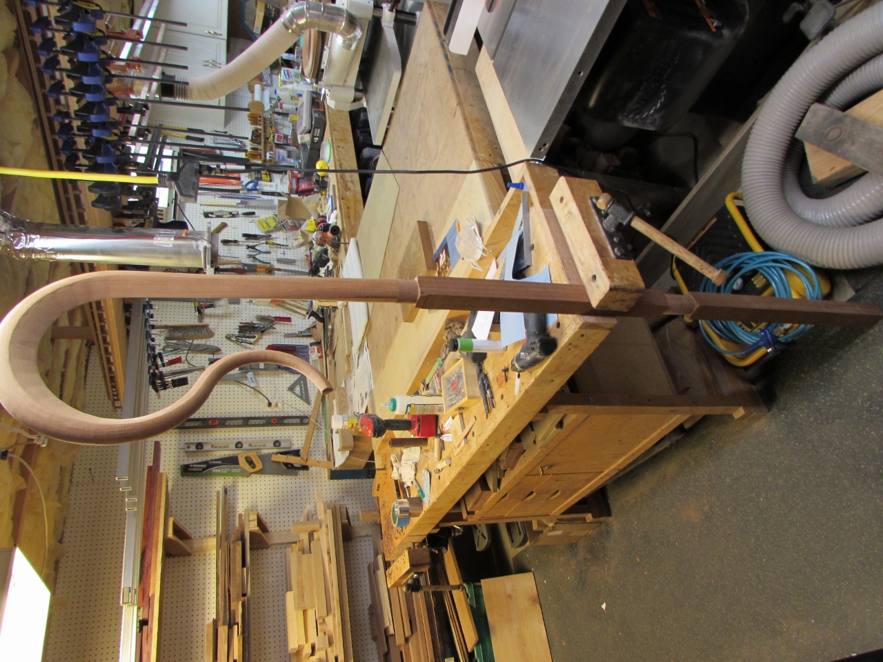
A little more final tweaking of the connection at the top and my part of this project was done.
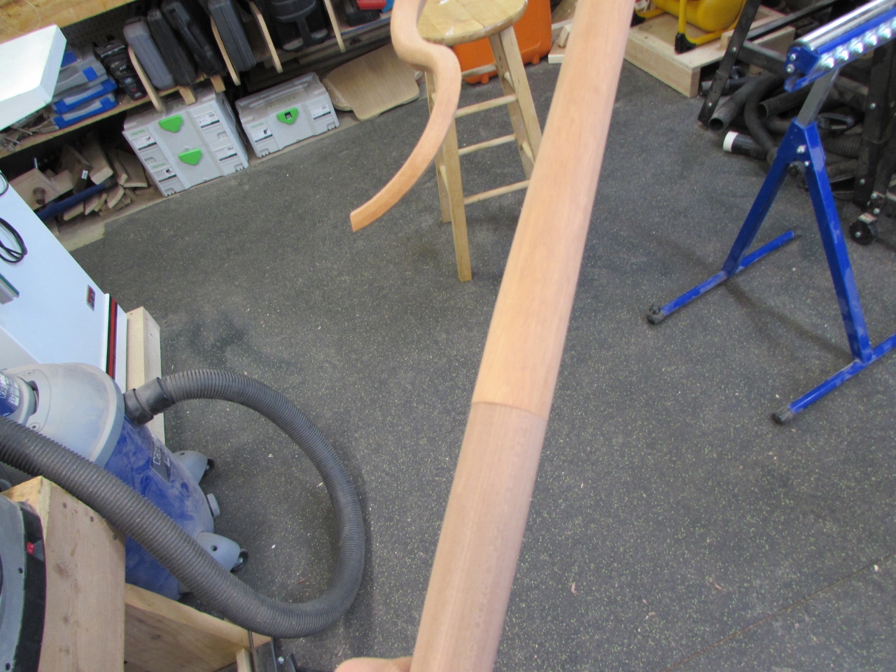
I handed the crosier back over to Dave. He worked with his machinist friend to correct the sockets and create a perfect connection, then did some finish sanding and staining. Unfortunately, the head piece dropped onto the floor, at one point, and broke off the re-curved end.
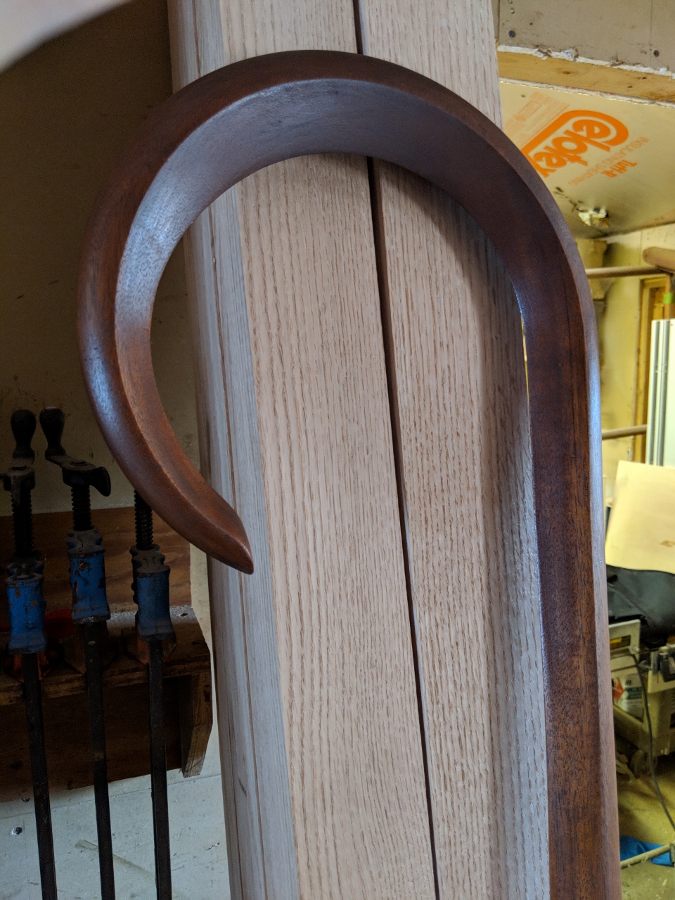
Instead of gluing it back on, Dave opted to sand the remaining end and keep it the way it is. I think it was a good choice.
This was an interesting project. I really like the magnetic connections, but I think the next time I need to make a similar connection, I will have to find a way to make it the tapered one, like my prototype.
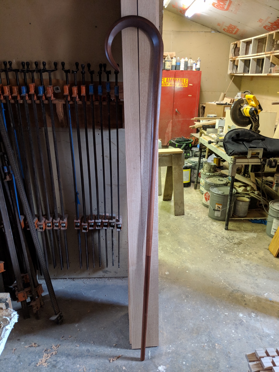
The crosier finished out about 6′-2″ tall and about 2-1/4″ thick across the top, tapering down to 3/4″ at the bottom. The three sections separate and fit easily into a mandolin case for transport.

Pingback: Bishop’s Crosier Rev 2 | Midnight Woodworking
Beautiful Crosier – my brother has just been elected a Bishop and he is looking for something simple. Is Dave able to make another? If so, how long does it take him to create it and approx. what is the cost?
Thanks very much.
Elena
I think my buddy Dave is trying to retire. That said, the last crozier I made was $1,500. There is more labor involved than you might think. If you were looking for something simple and inexpensive, I have seen them online for $200 to $500 on places like eBay and Autom. Hope that helps.