
Backlight office sign – week 3
At first glance, installing these LED lights seemed rather straight-forward. But, like everything else I do, the harder you look at it, the more complicated it gets.

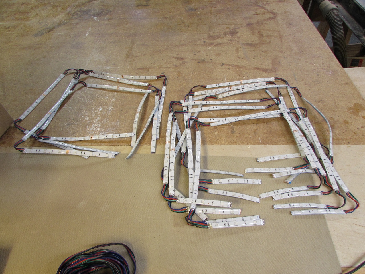
Hind-sight is a great teacher. It might have been smarter to build a prototype of a single tile of this sign and then outfit it with LEDs. This would have probably made me consider a slightly smaller tile, or perhaps I would have explored other brands. Of course, where would the challenge be in that? First key factor, is the length of your LED strip. I purchased a light strip kit from Amazon. It came with a power supply, controller, remote, and (2) 16.4′ long rolls of LEDs. First thing to note is that you cannot chain all 32.8′ of LEDs together. The controller is split so you can only circuit up 16.4′ of LED to each leg of the controller. Each strip can only be cut every 4″ (where marked). While that seems pretty easy to work with, it is hard to get an even light spread around the corners if you have to stop a couple of inches short. They sell clip-on connectors that will connect around corners, but that gave me two problems. The first was that when clipped on, the total overall square of LED was about 9″x9″ and my LEDs needed to be at the outer edge of an 11-1/4″ square. The second problem was that the connectors were junk. They connected up okay, but the moment you moved anything, they could lose contact and the color of the light would change depending on which leg of the circuit lost contact. I realize the sign sets still, but it is still mounted vertically and over time, I fear something will sag.
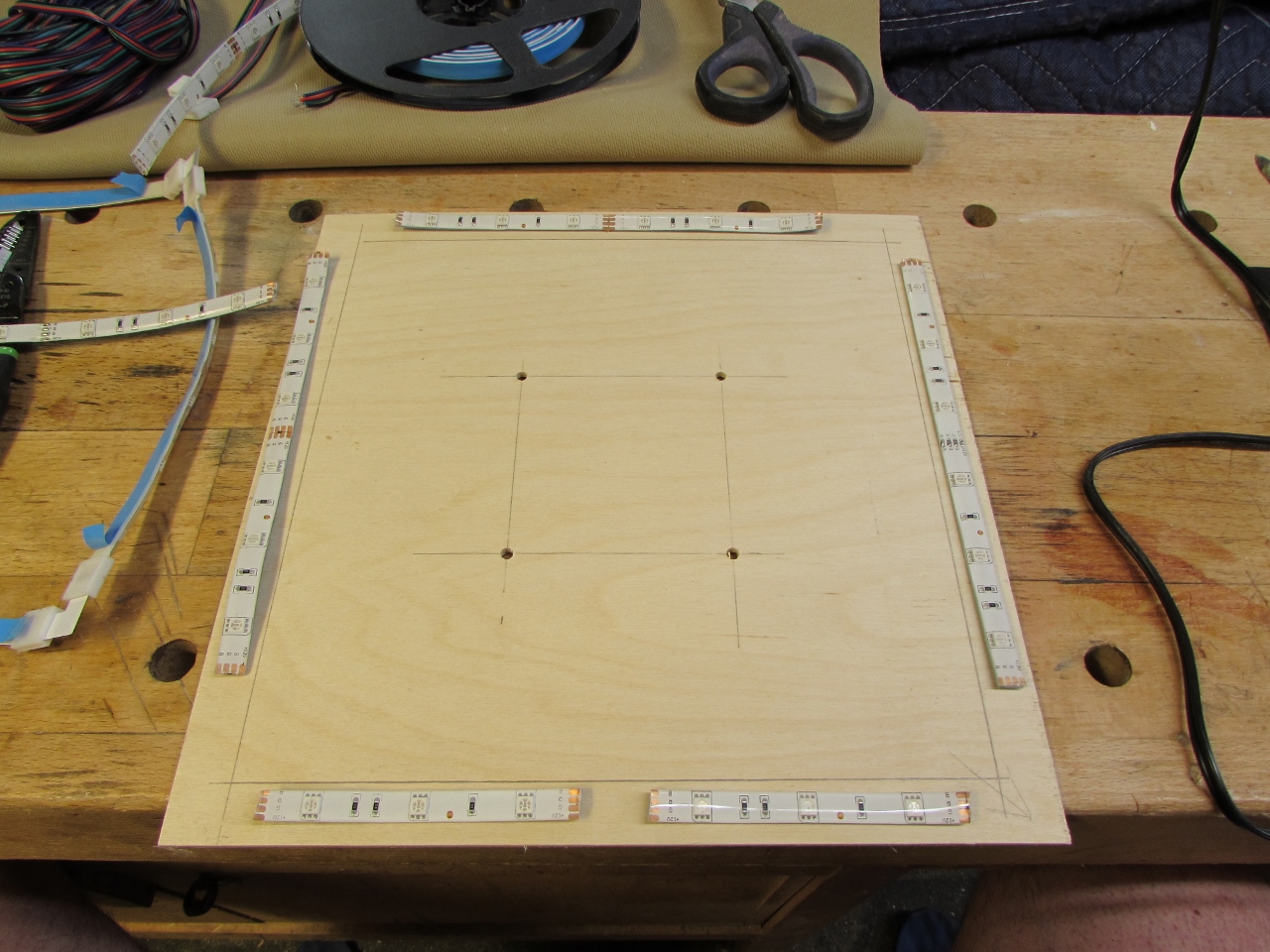
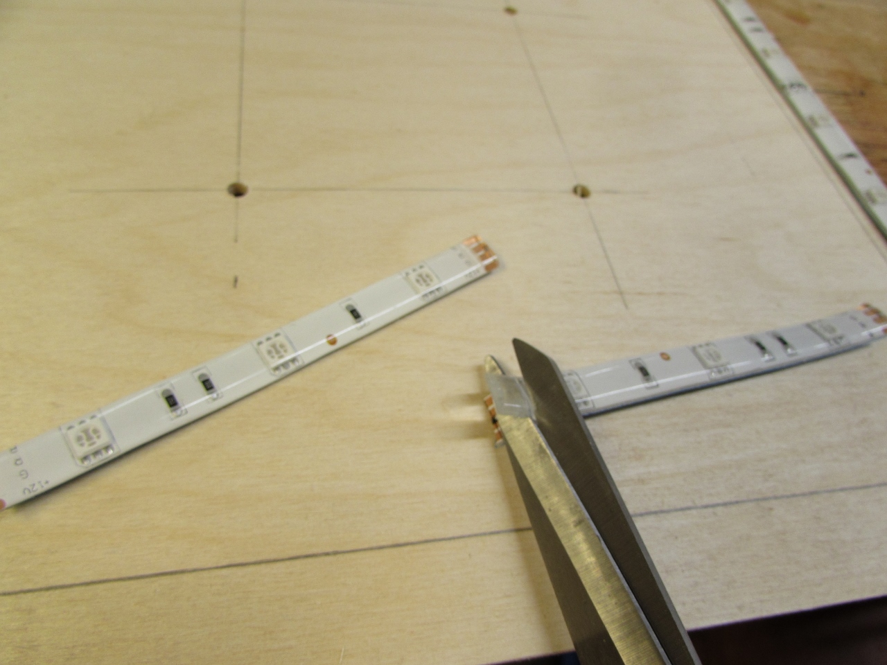
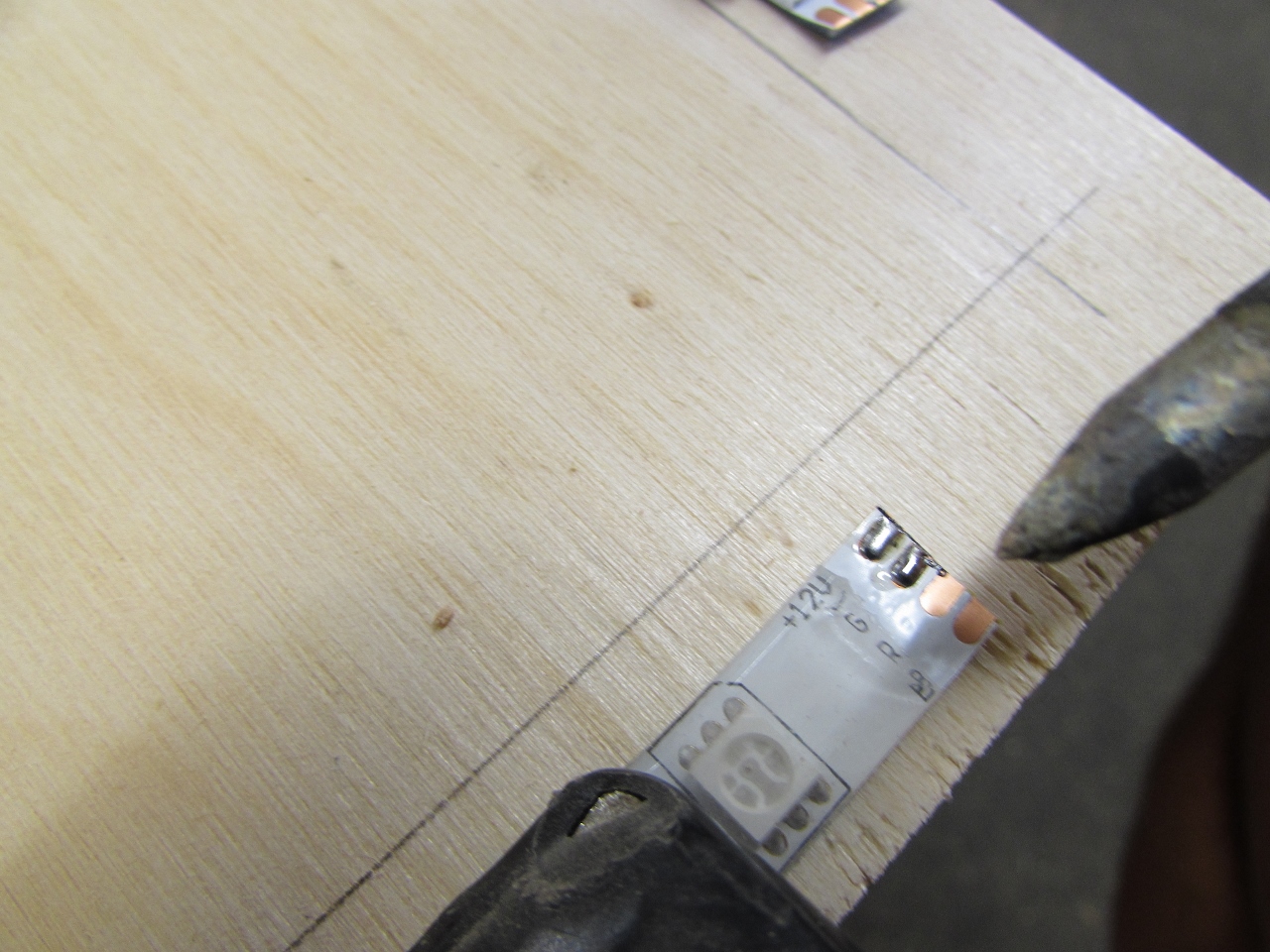
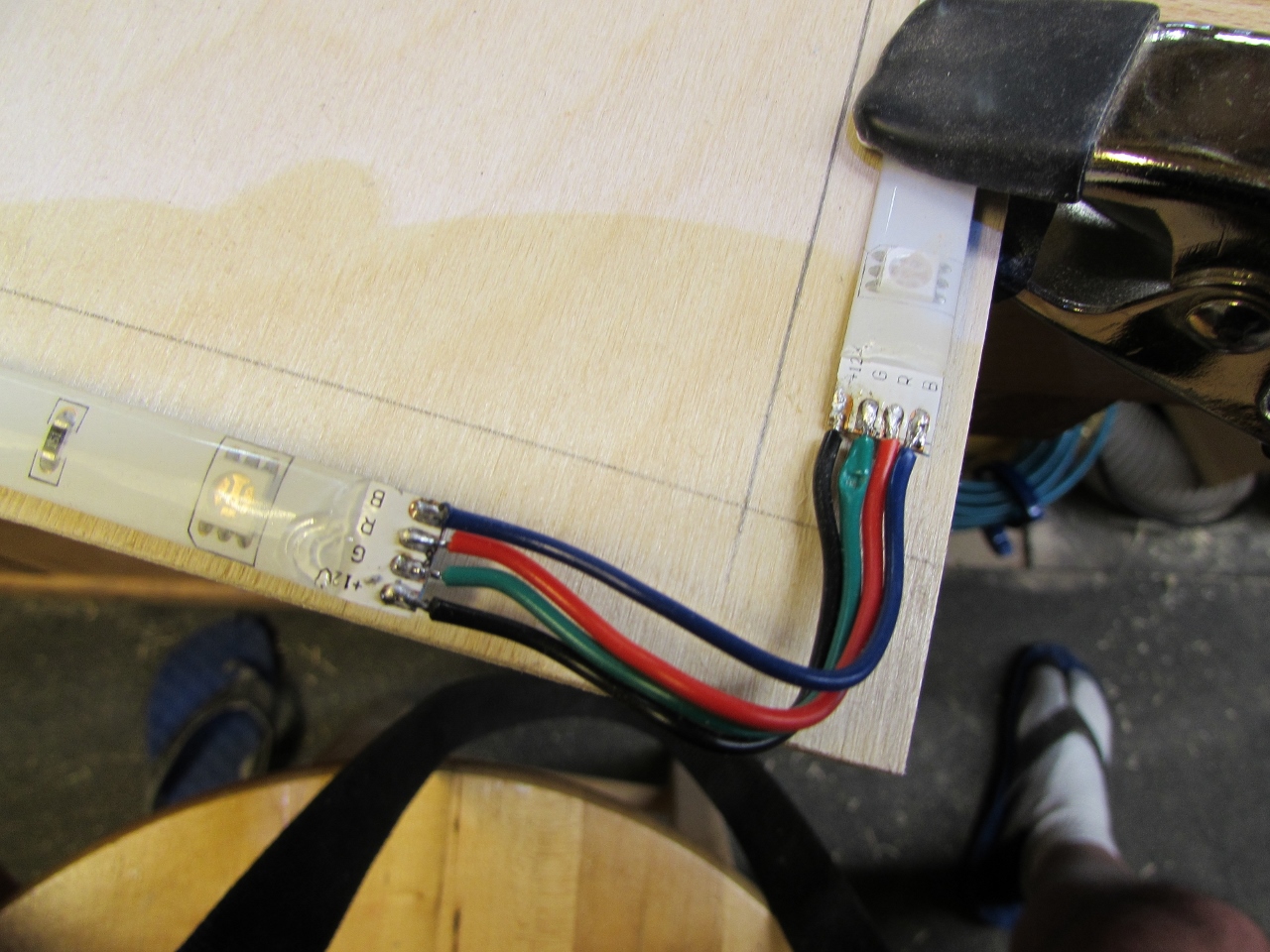
The best option I could think of was to cut a 2-1/2″ strip of wires and solder each corner together. Since these are outdoor rated, I had to peel back some silicone from each contact and trim it away.
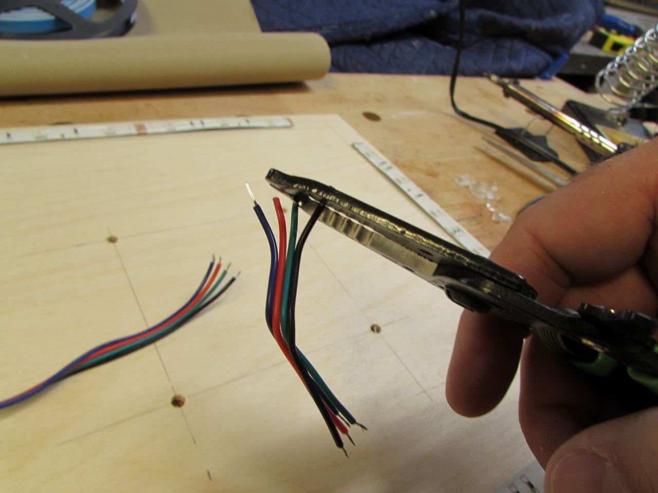
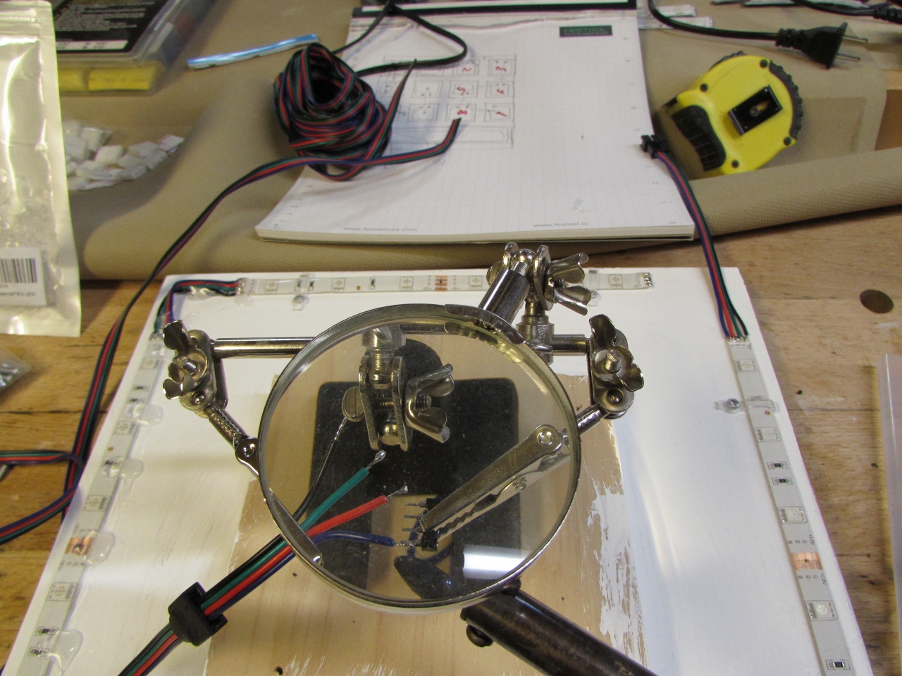
Keep in mind, I have only soldered a couple of guitar controls. I am not an electronics guy. I went through a lot of trial and error getting a system down that was accurate and repeatable. I started by stripping, twisting, and tinning (soldering) the end of the wires, then trying to solder them to the contacts. It still needed more solder to attach well, but that would have required three hands. Finally I thought to add solder to the contact first. That worked really well. It beaded up just high enough that I could sink the wire end down into it.
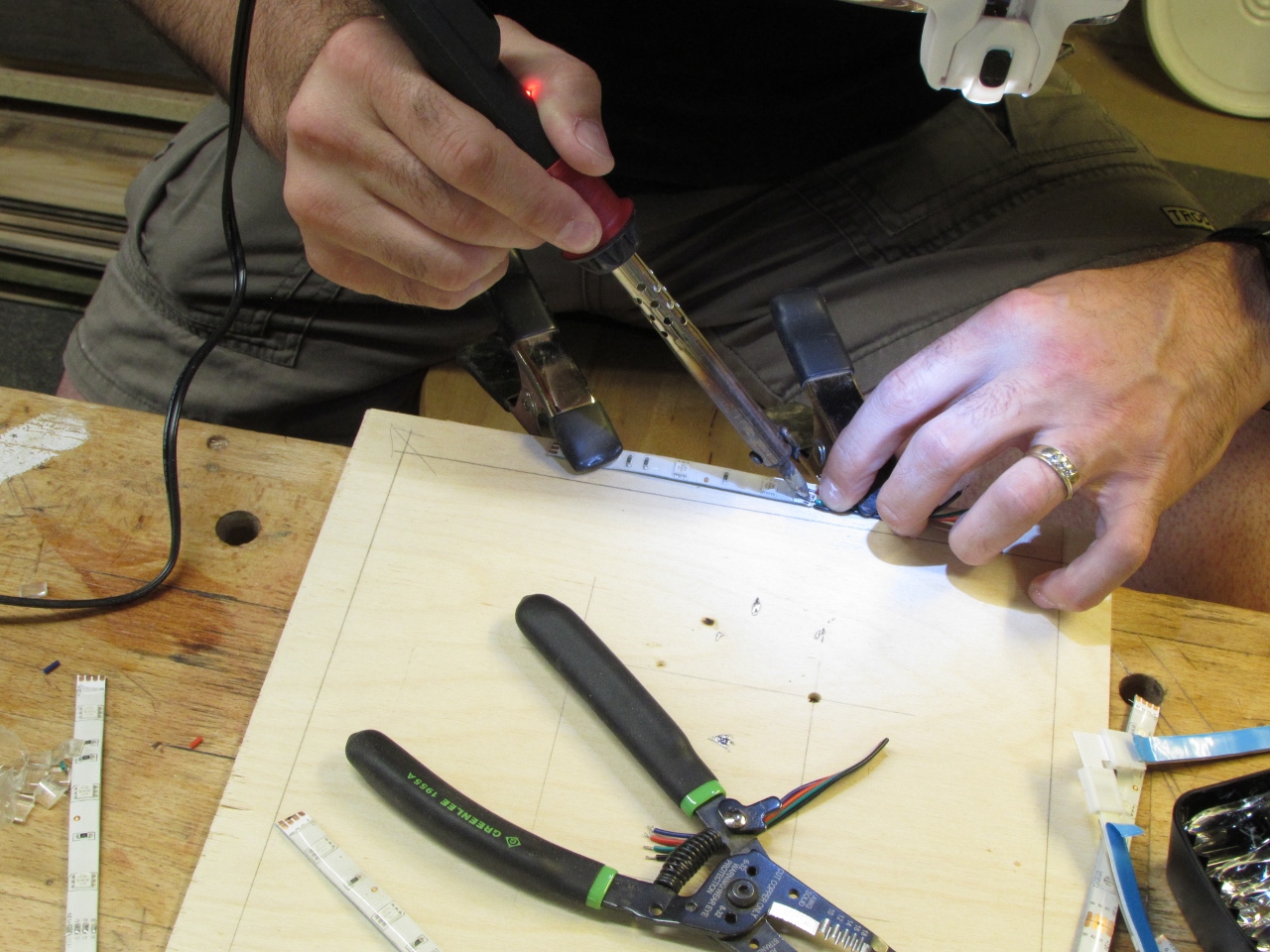
I had to purchase some head-mounted magnifying glasses to be able to see that none of the solder crossed over to any other contacts.
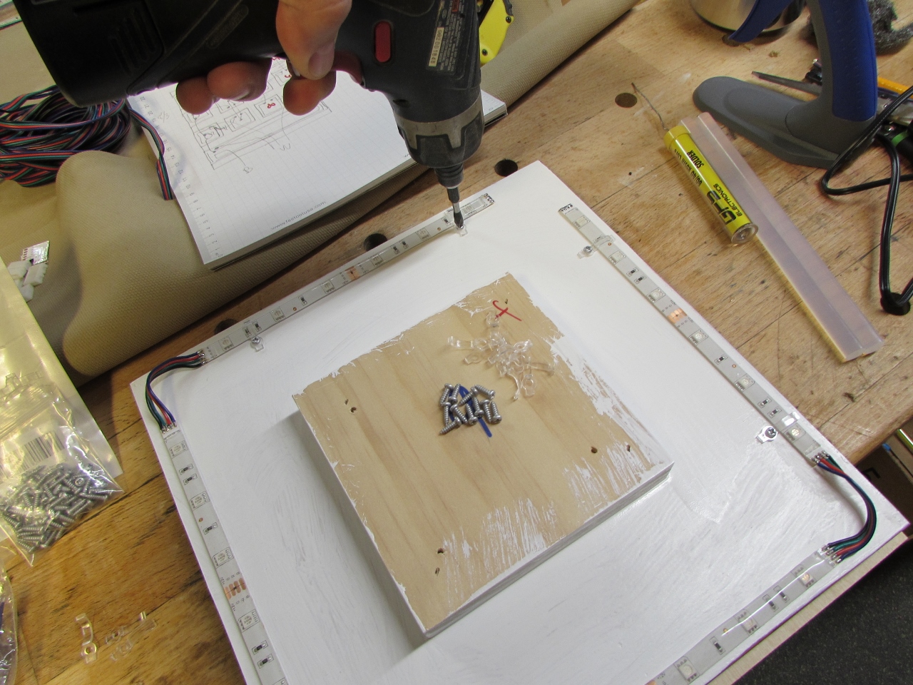
It was rather tedious and took me about an hour each to circuit a tile. I used a mock-up piece of plywood to lay out each circuit, thinking that any damage caused by the soldering iron would not be on my tiles, but in retrospect, it would have been way easier to stick the strips in place and solder them.
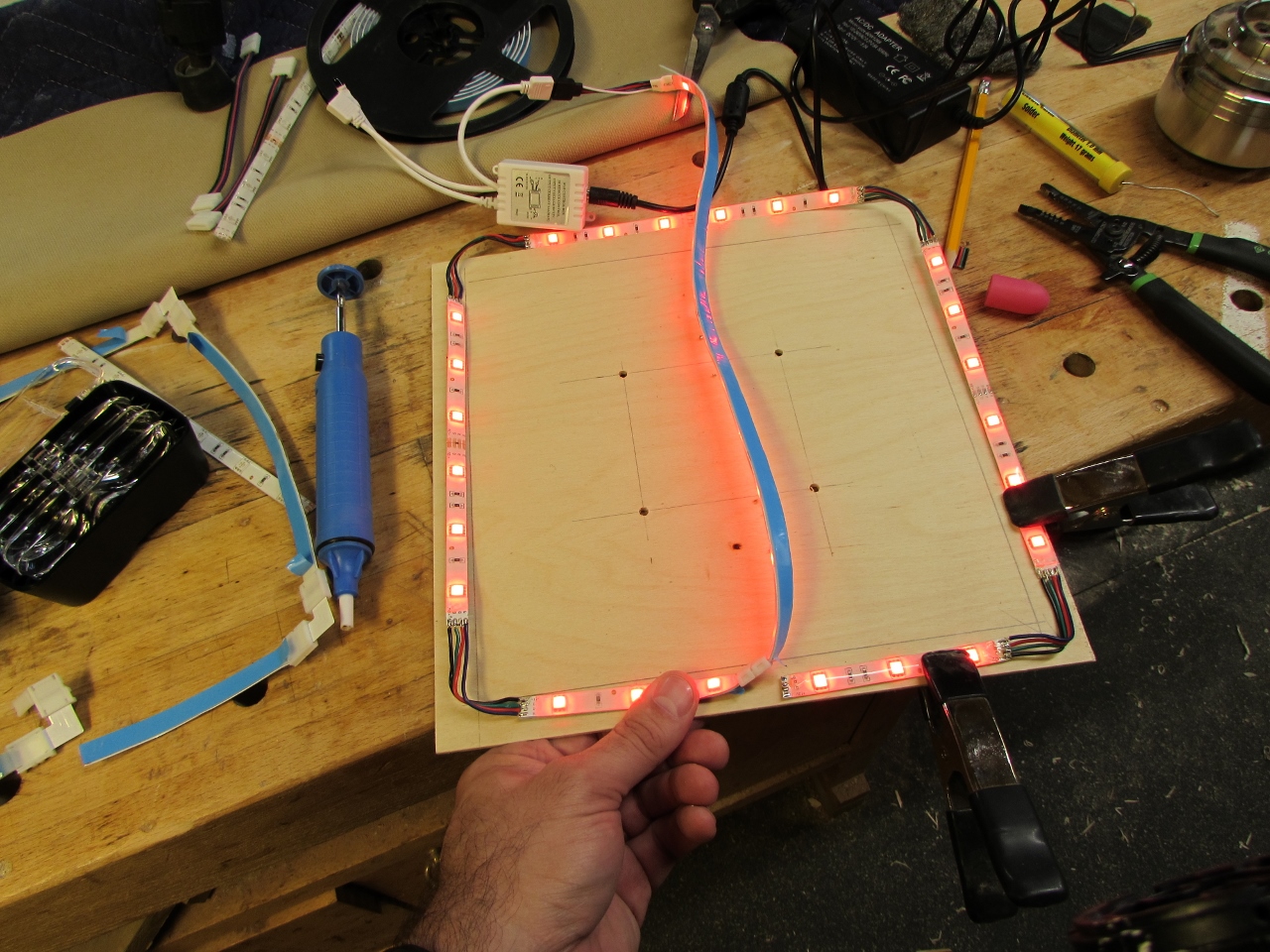
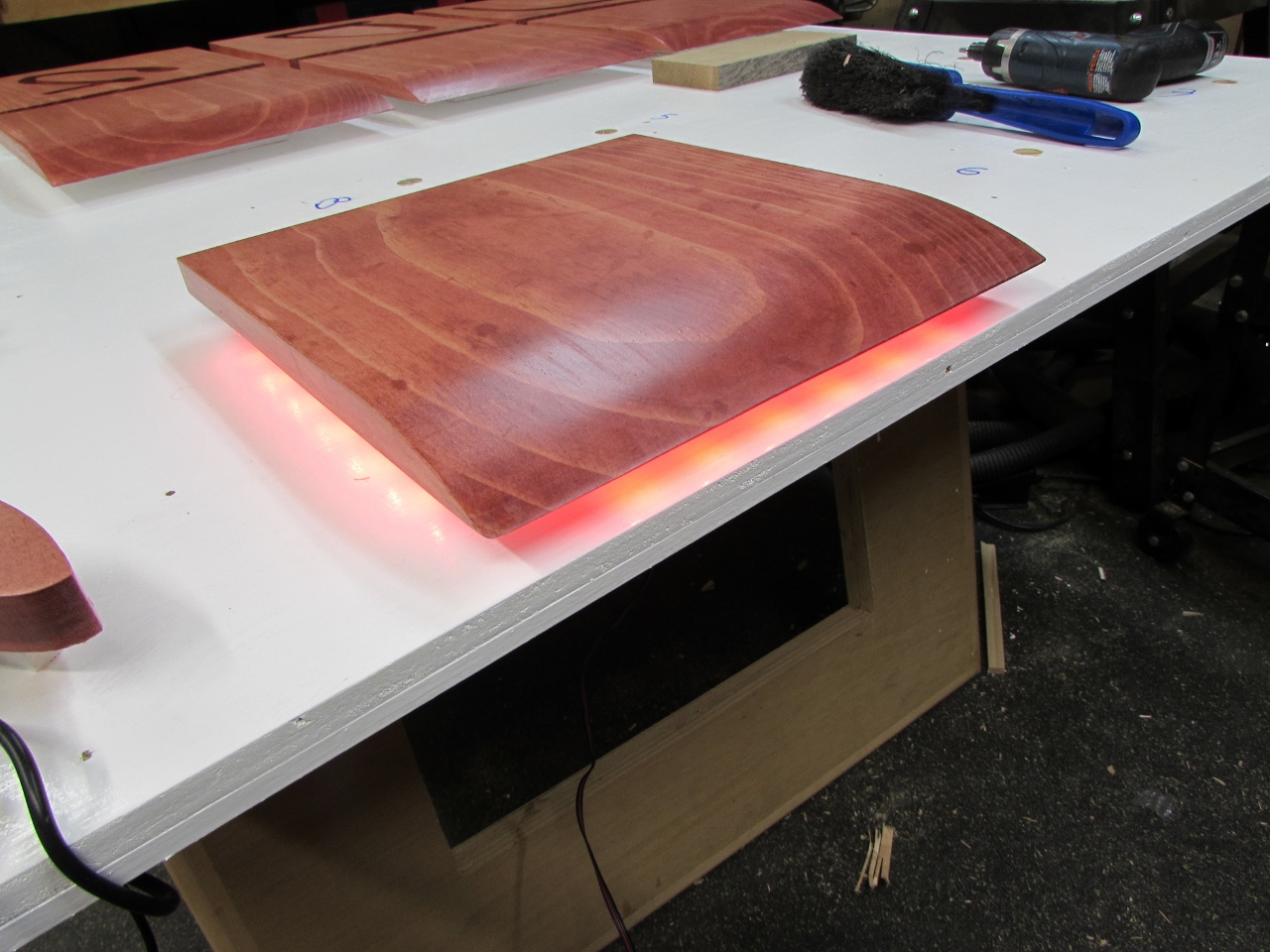
I finished the first circuit and tested it out. Success! I also made sure to test Red, Green, Blue, & White. If there is a bad connection, the colors will not mix right, but you wouldn’t know it if you did not test all of them.
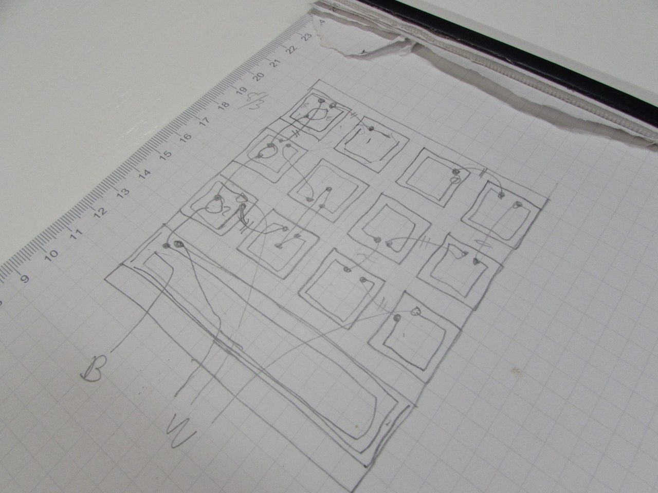
With the first one done, I created a circuit layout and made up the other eleven circuits. I didn’t bother taking additional pictures, it was about 10 hours of fun… Not! Again, I am not very fast at this.
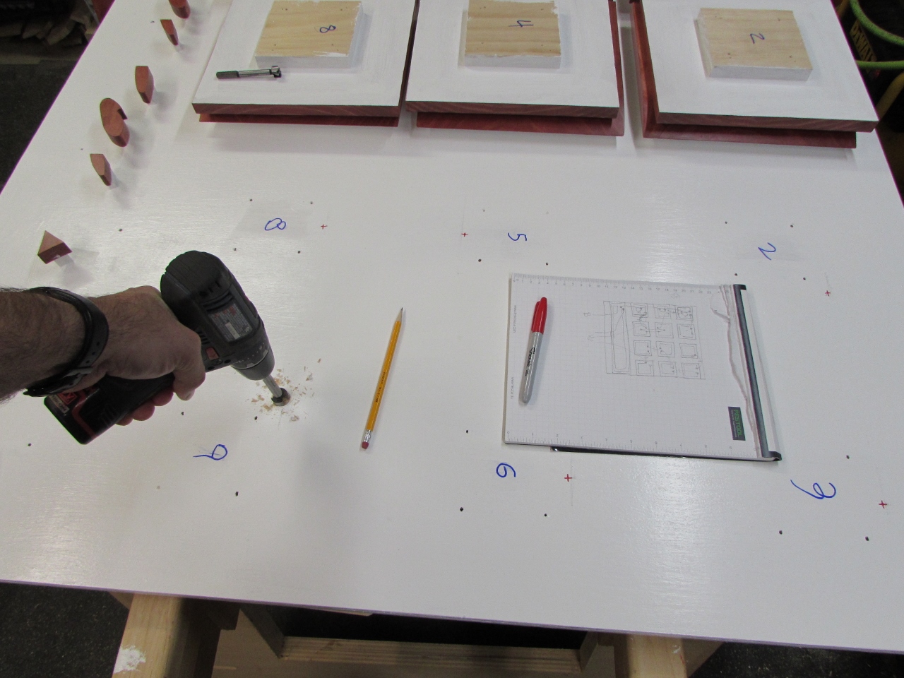
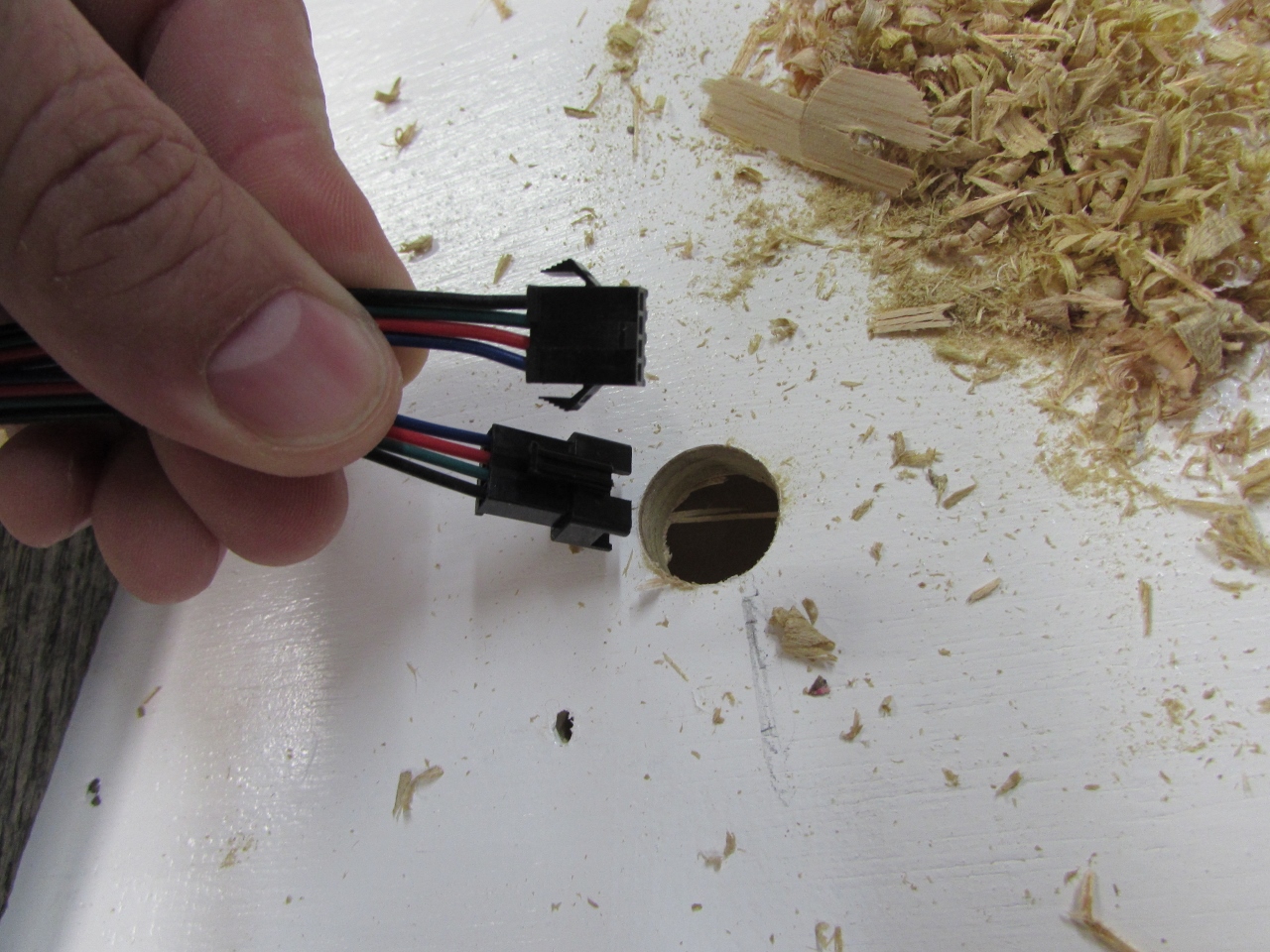
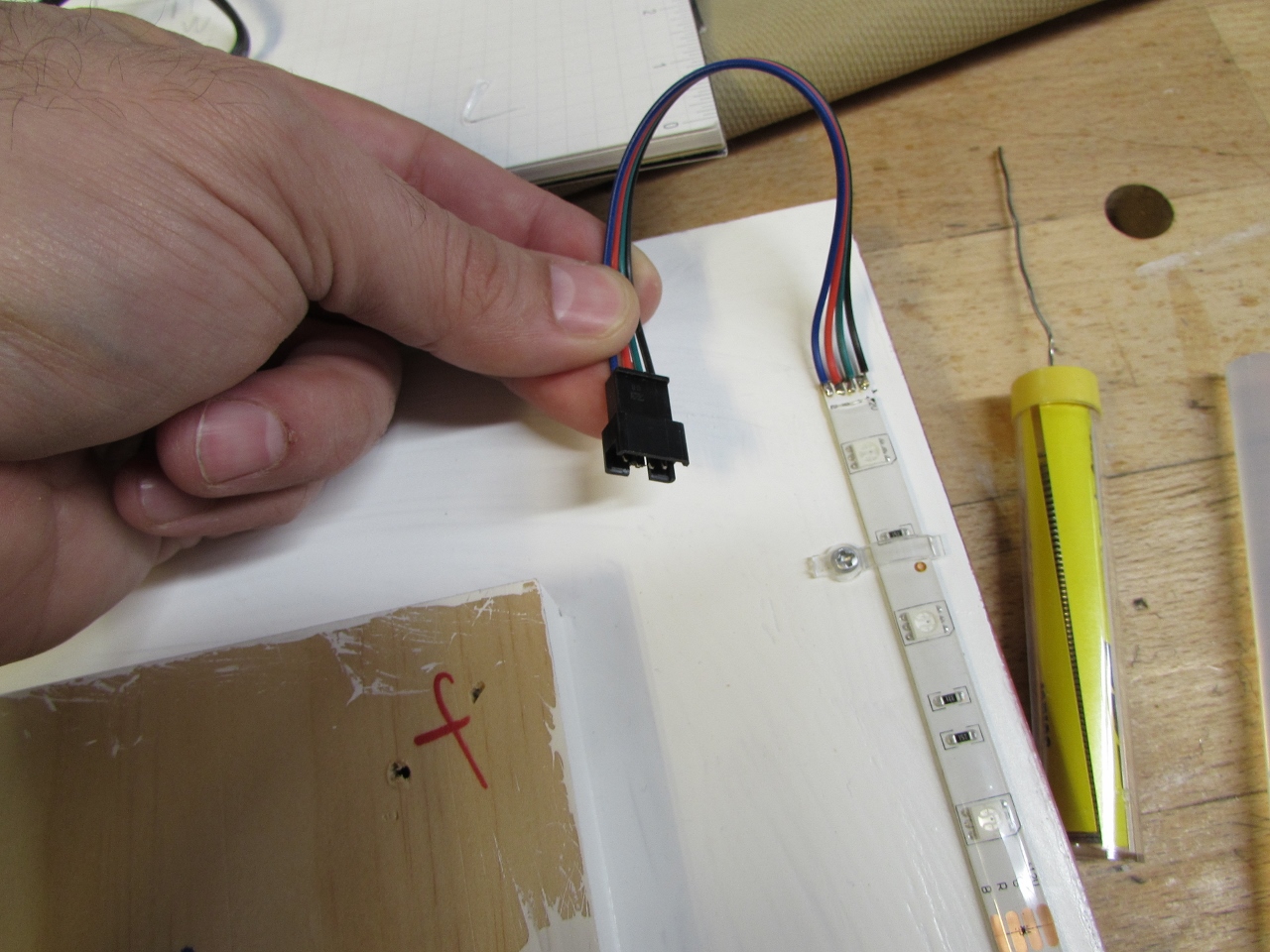
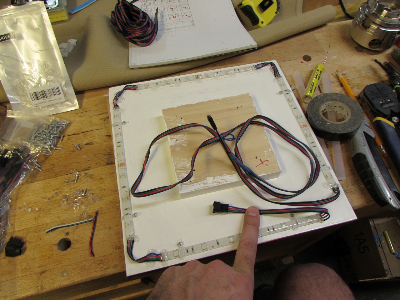
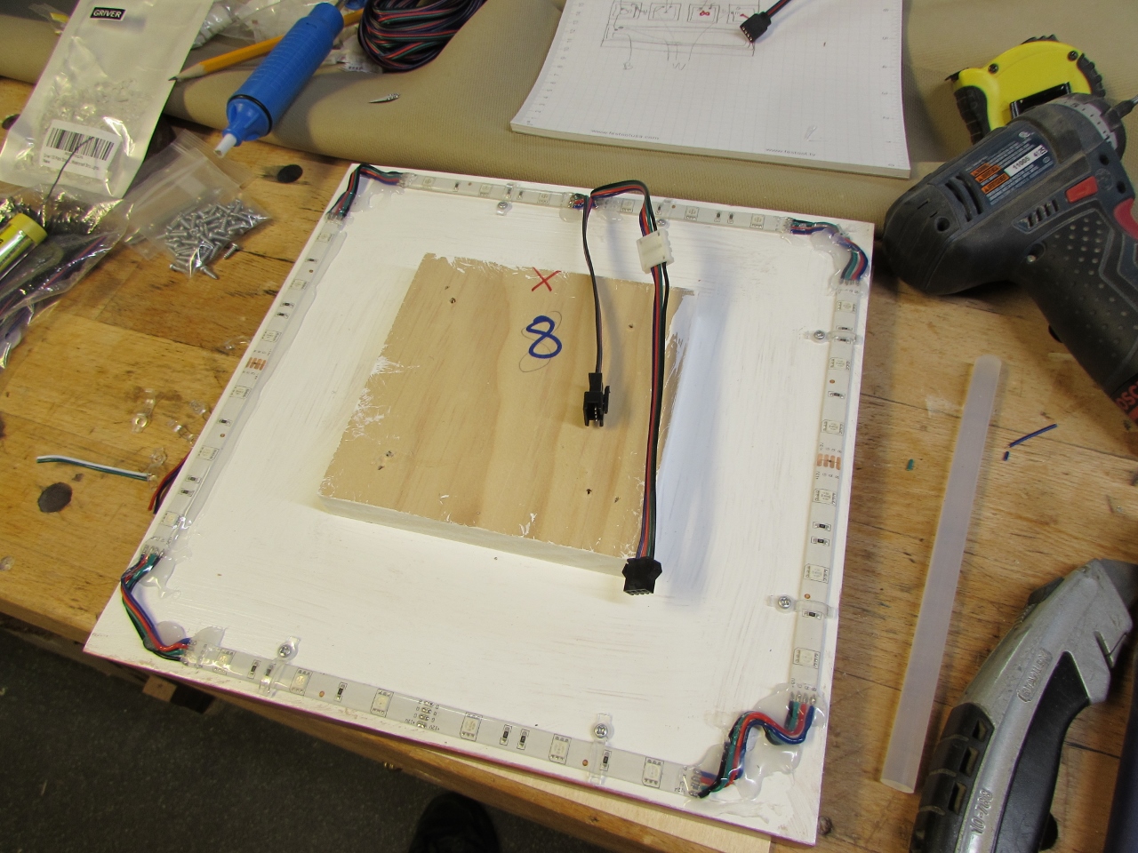
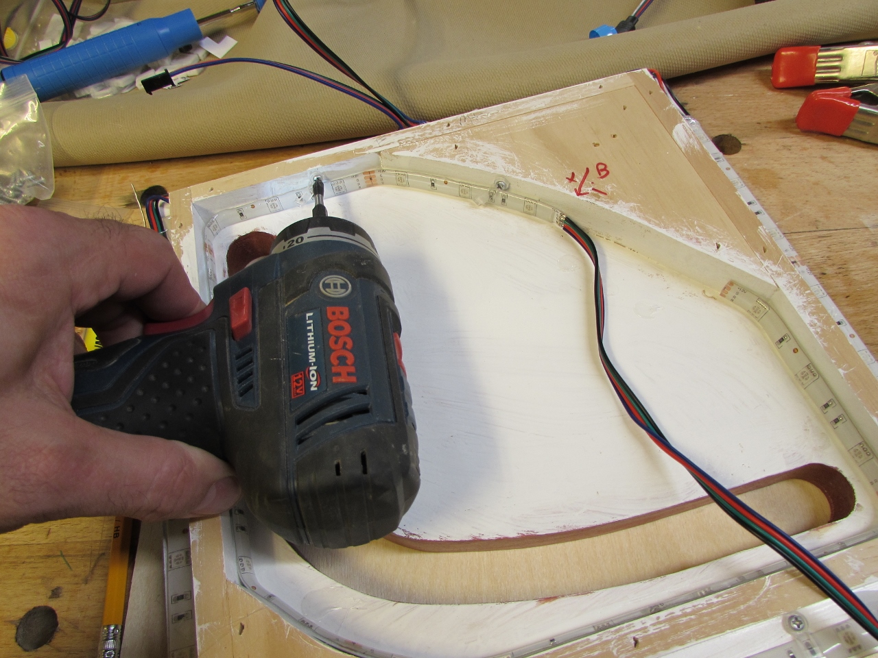
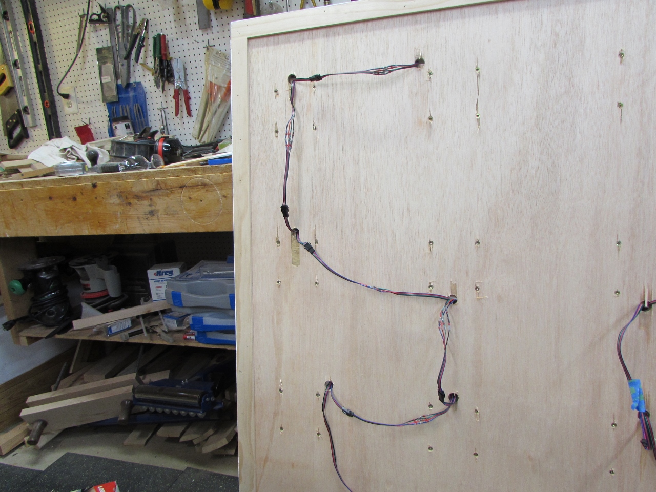
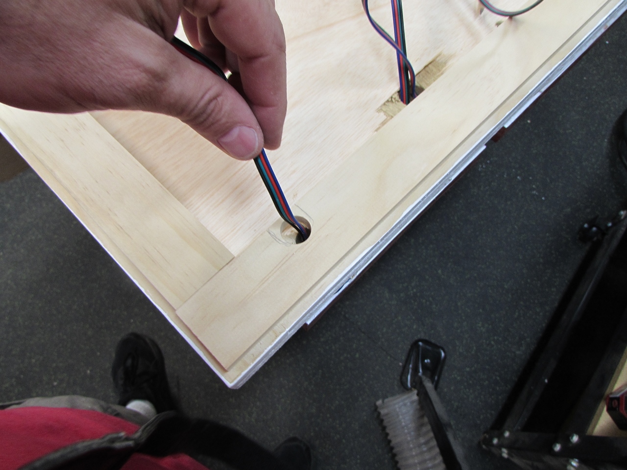
With the circuits done, I started figuring out where the holes needed to be drilled to pass wires through. To connect each tile together, I bought some 4-pin connectors that had a 5/8″ wide head. I drilled a 3/4″ hole through the back board, tucked in close to the tile stand-off so it was out of sight.
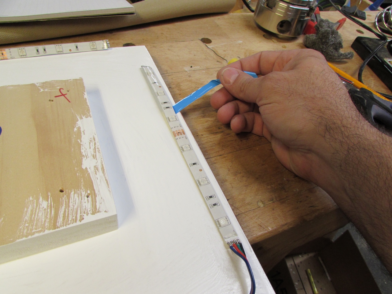
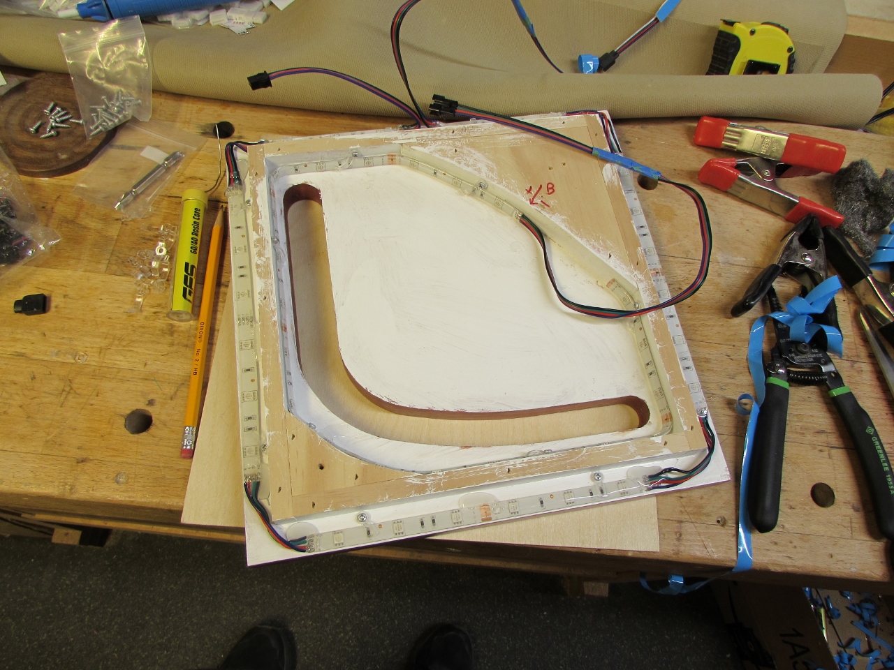
I peeled the backer off the LED strips and installed them on the tiles, then screwed down some retainer clips because I don’t trust the double-sided tape on the LEDs.
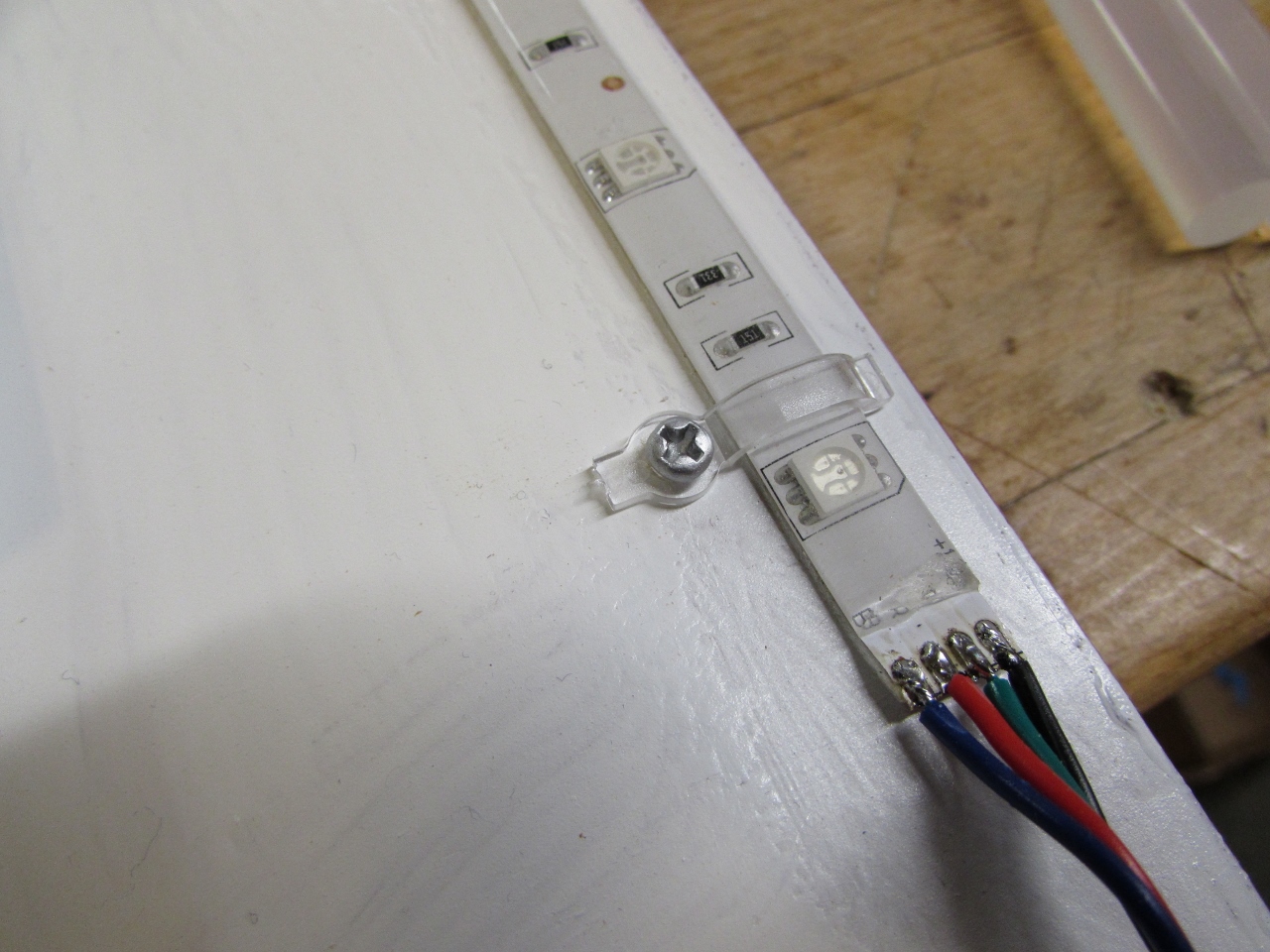
Next I soldered on the male and female connectors.
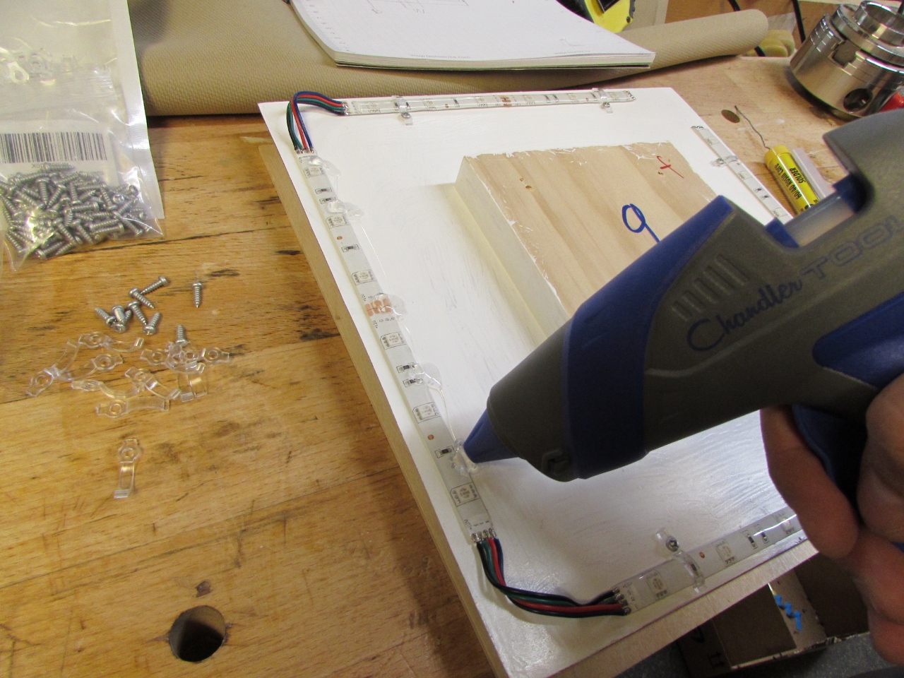
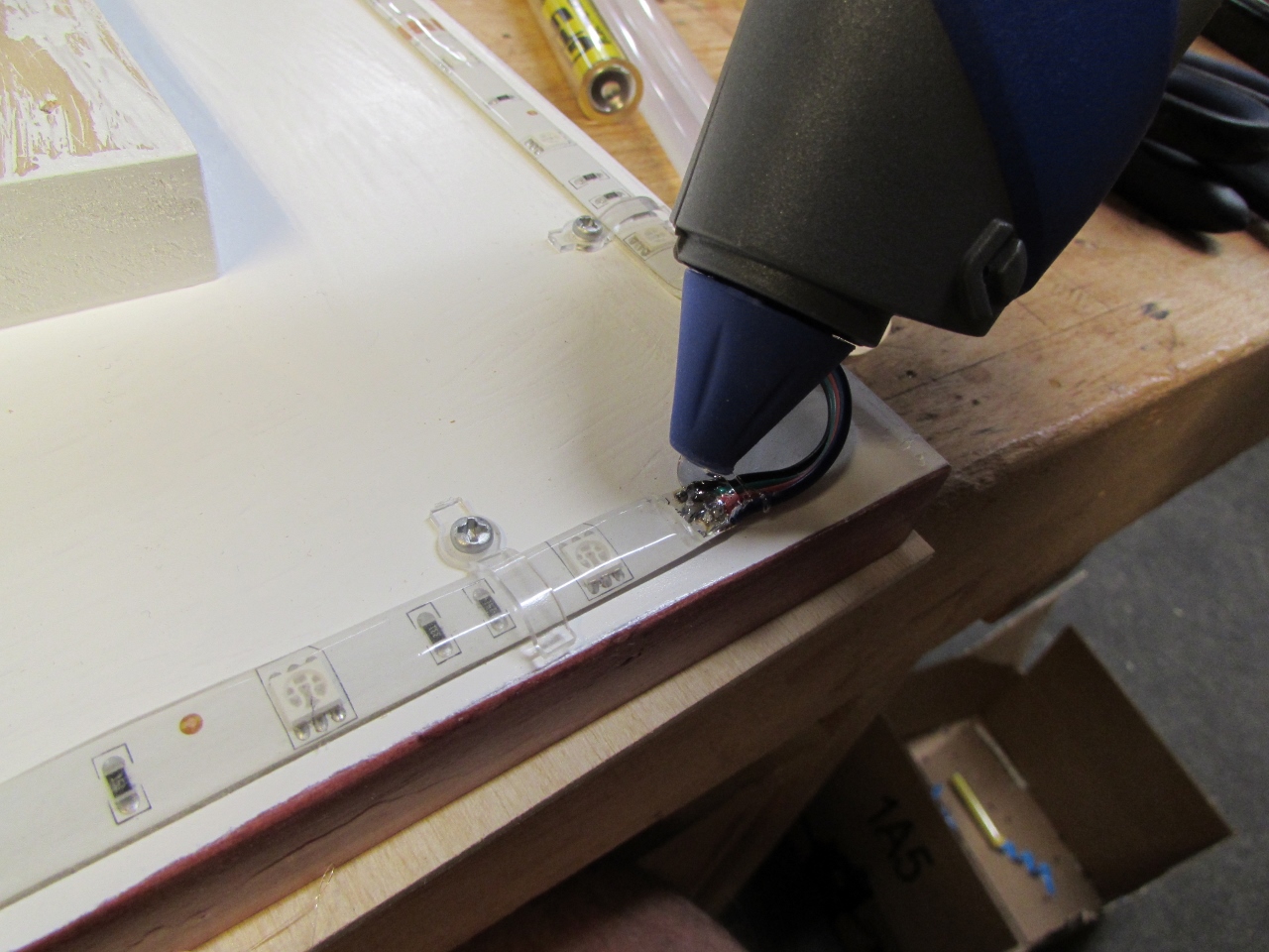
Then applied a bead of hot glue to each of the solder joints as an insulator. These are low voltage, but I don’t like bare contacts.
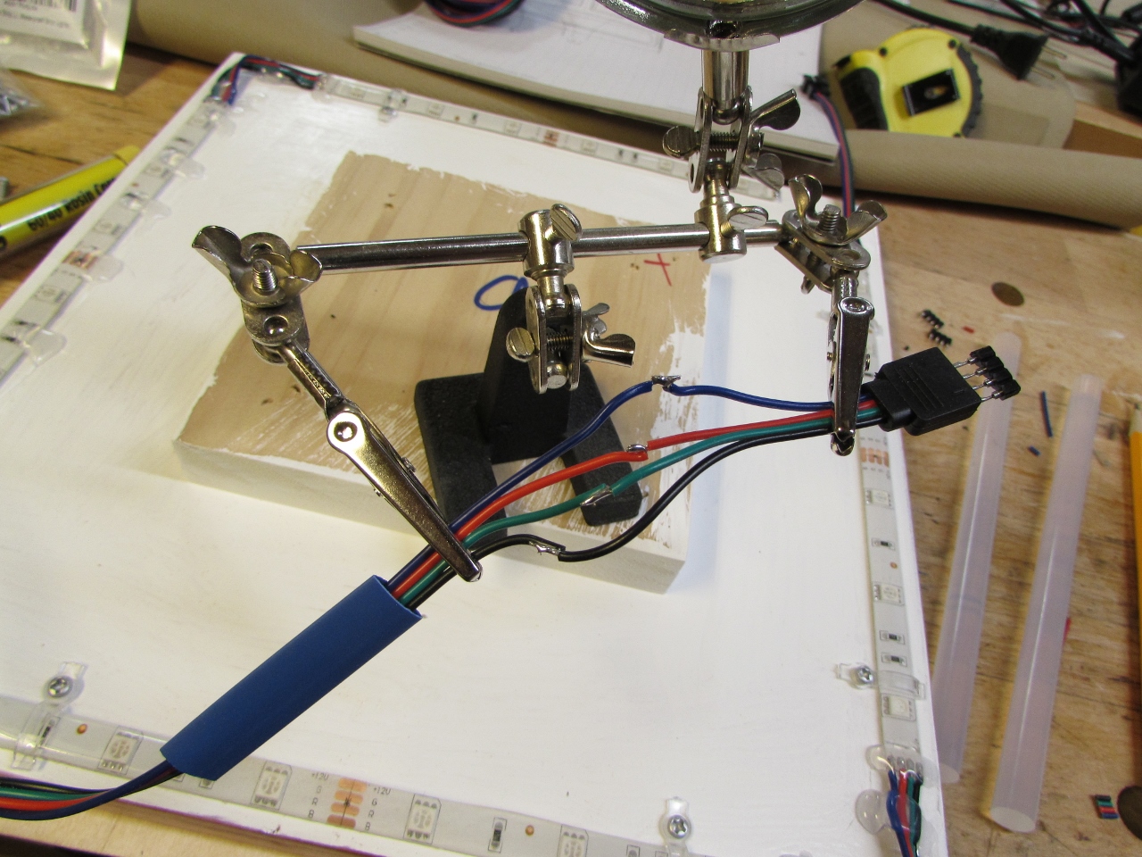
For the first tile, I had to add a longer wire that would plug into the controller. I thought I could just solder the wires to the 4-pin connector, but my skills were lacking and I melted the thin plastic around the pins every time.
So I had to buy some pre-wired connectors and connect them to my wire. This also proved to be a pain. I opted to stagger each connection, twist both wires together, solder them, wrap each connection with a small amount of electric tape, then cover with a heat-shrink sleeve.
The whole thing took me about 20 minutes or more, so I started looking for a better way. More on that later.
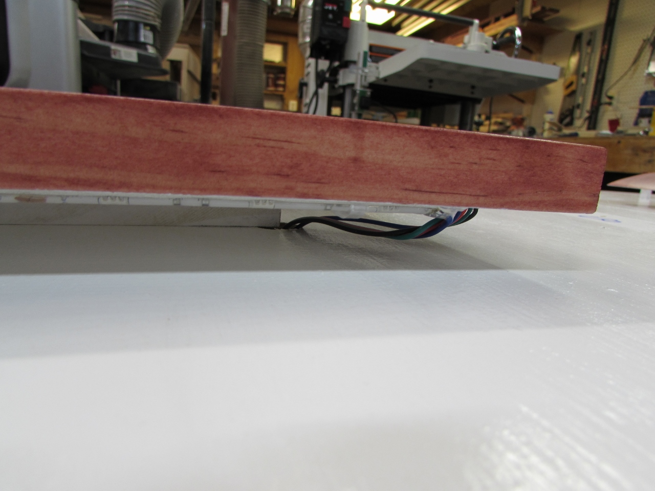
Finally the first tile was ready for install, and I fished the wires through and screwed the tile back on.
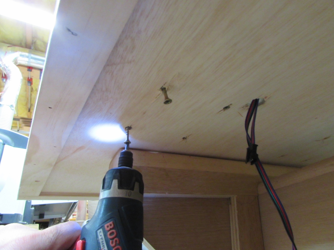
And, it worked. Praise the Lord! Only 12 to go…
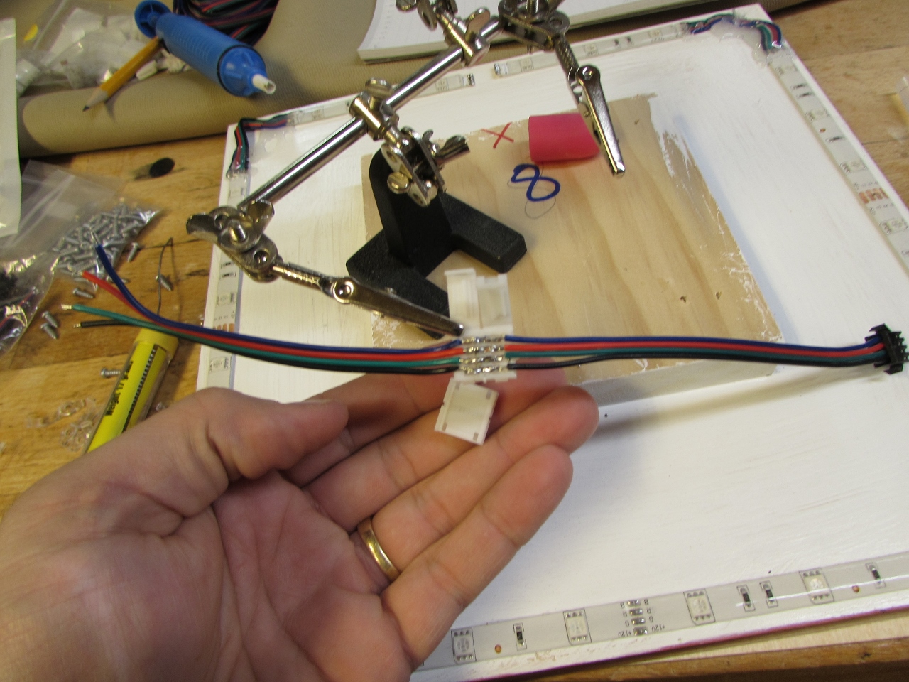
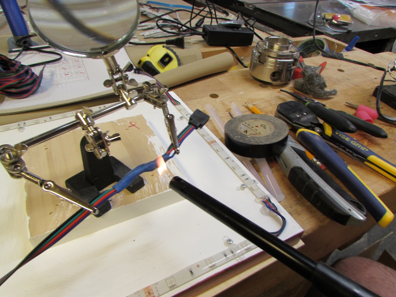
The male/female connectors, that I bought to connect the tiles, are too short to reach the next tile, so I have to add an extension. I didn’t want to repeat the method I just tried so I grabbed one of my left-over click-on connectors and tried soldering the wires to them.
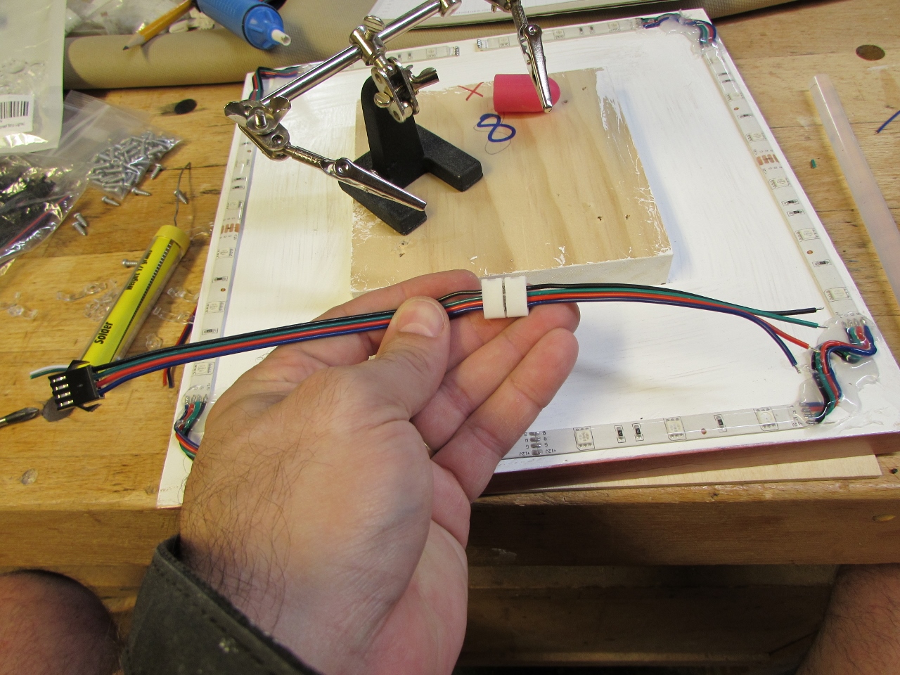
Worked pretty good for a while, then I realized some of the connections failed when the clips were closed. So I put off that connection till later and just taped the connectors to the extension wire until they were all done. The tape will help me keep track of everything until all is attached to the backer board and I can work on splicing them all together from the back side.
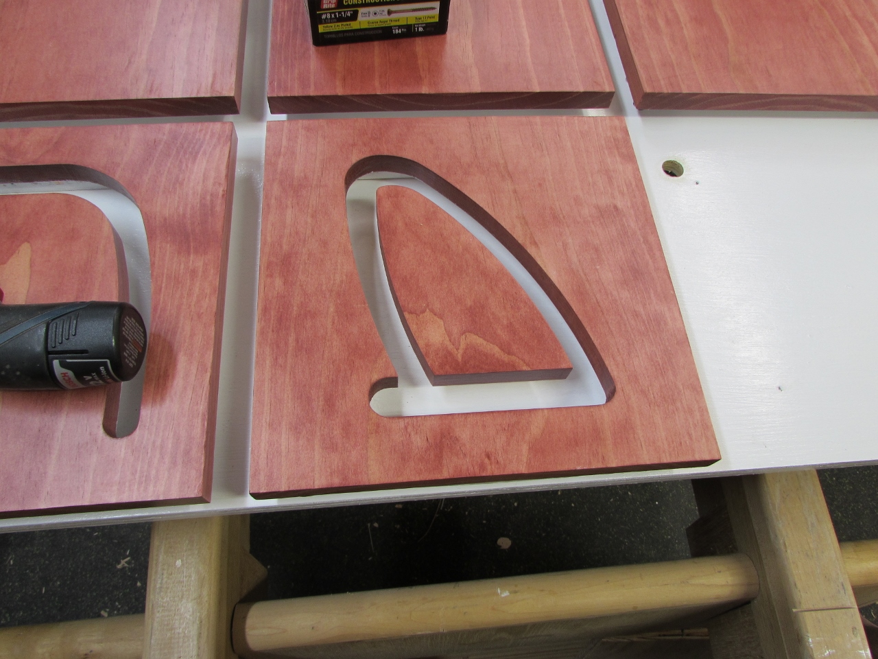
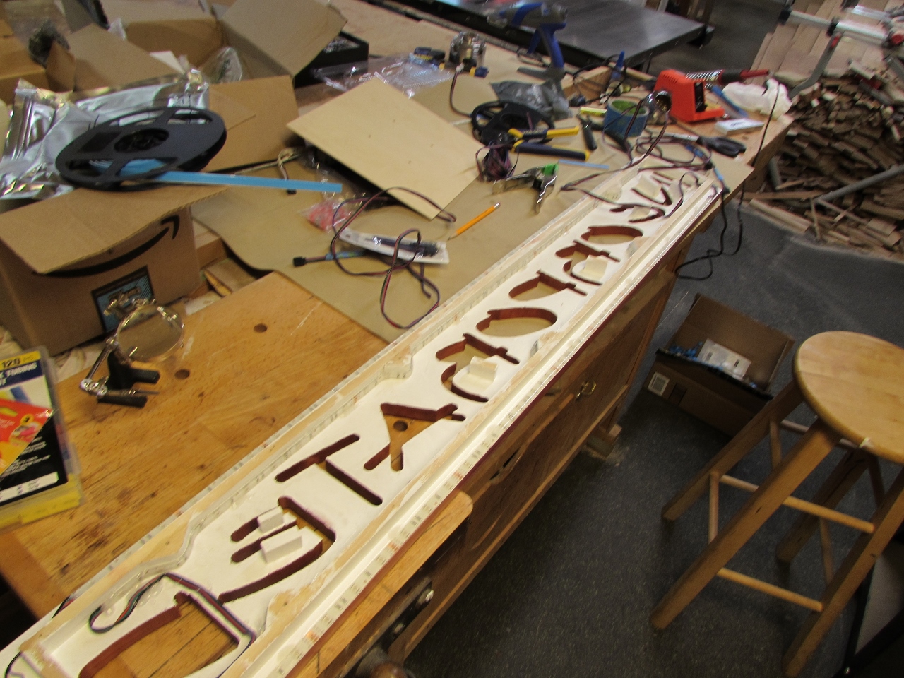
Several days later, I was down to the last three tiles with the big letters in them. Things are a little tighter around the stand-offs so I had to trim down my clips with a pair of scissors so they could be installed.

These get a separate circuit, around the inside, for a different color. The strips were a bit more difficult to install because they went on sideways.
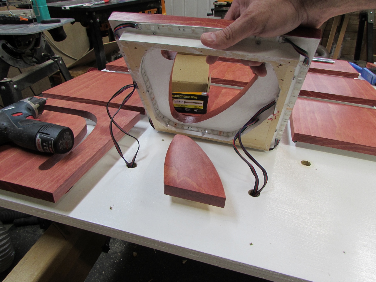
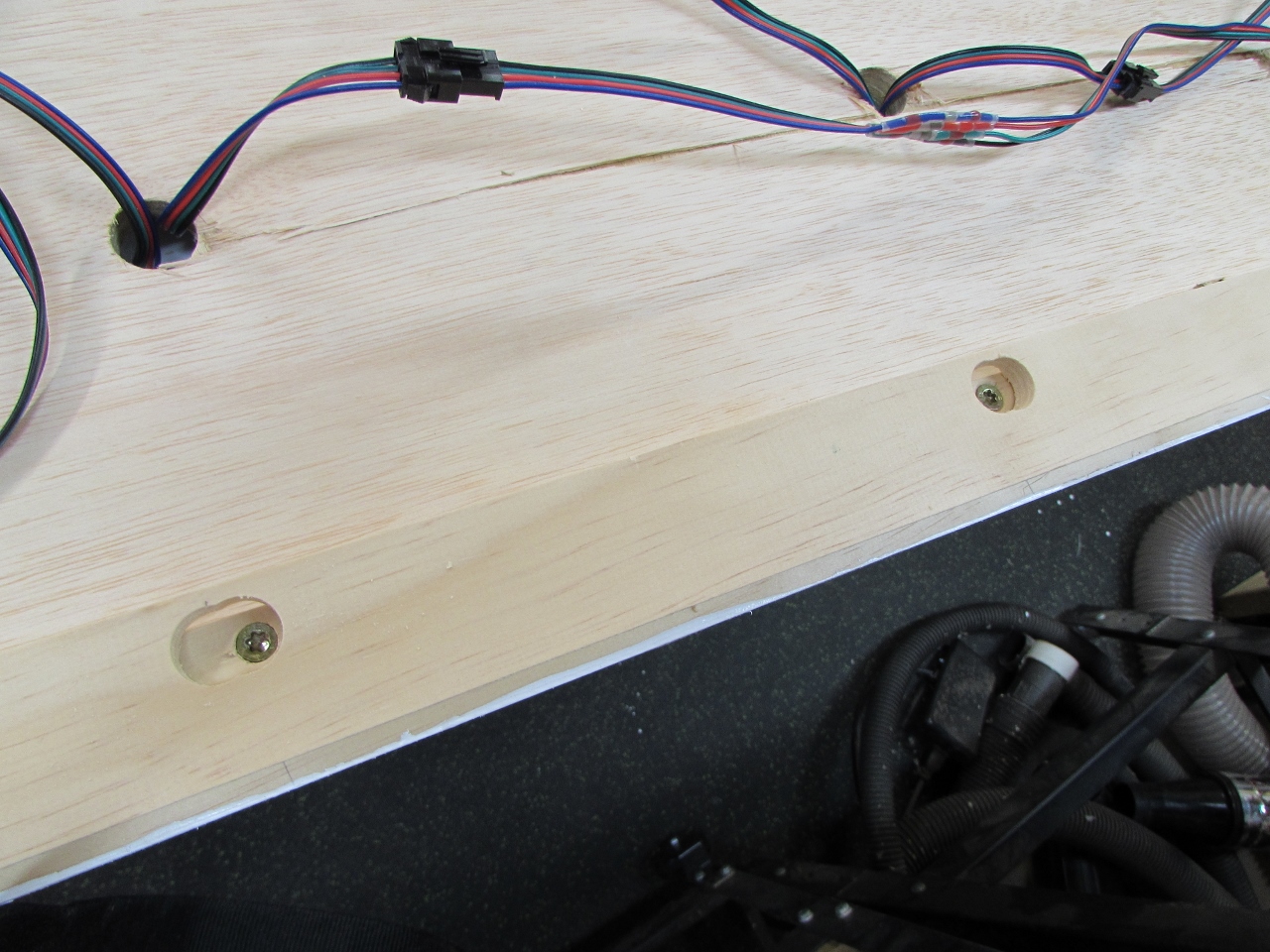
I have a separate through hole for each color, mainly to keep the wires out of sight.
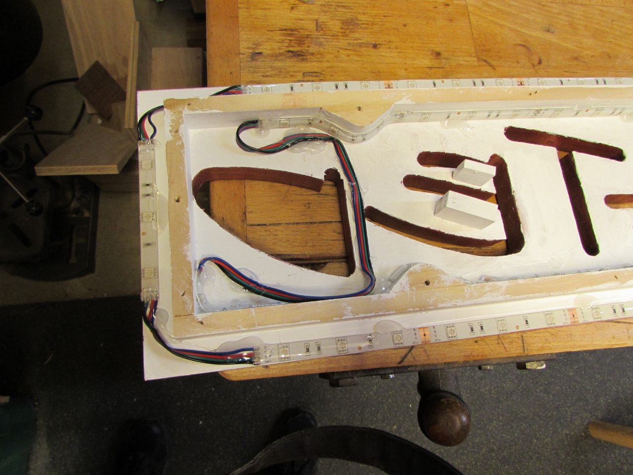
The last tile to wire up was the biggest one. I had to carefully rout my wires between the letters and hold them in place with hot glue. But after an hour or so, I got that one wired up as well.
Hopefully I soldered everything up right because I haven’t been able to test any of the final connections. I was waiting on some new connectors that I ordered. They are water-proof solder seal connectors. They look like they may be a bit over-kill for indoor use, but I am tired of messing with these connections.
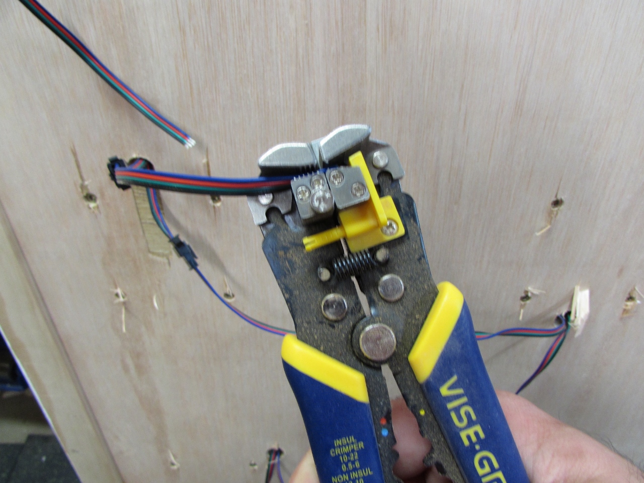
I was about 10 hours into stripping and soldering these tiny wires when I remembered that I owned a set of self-adjusting wire strippers that would strip all four wires at once. They just grip and rip the insulation off. OMG they would have saved so much time…
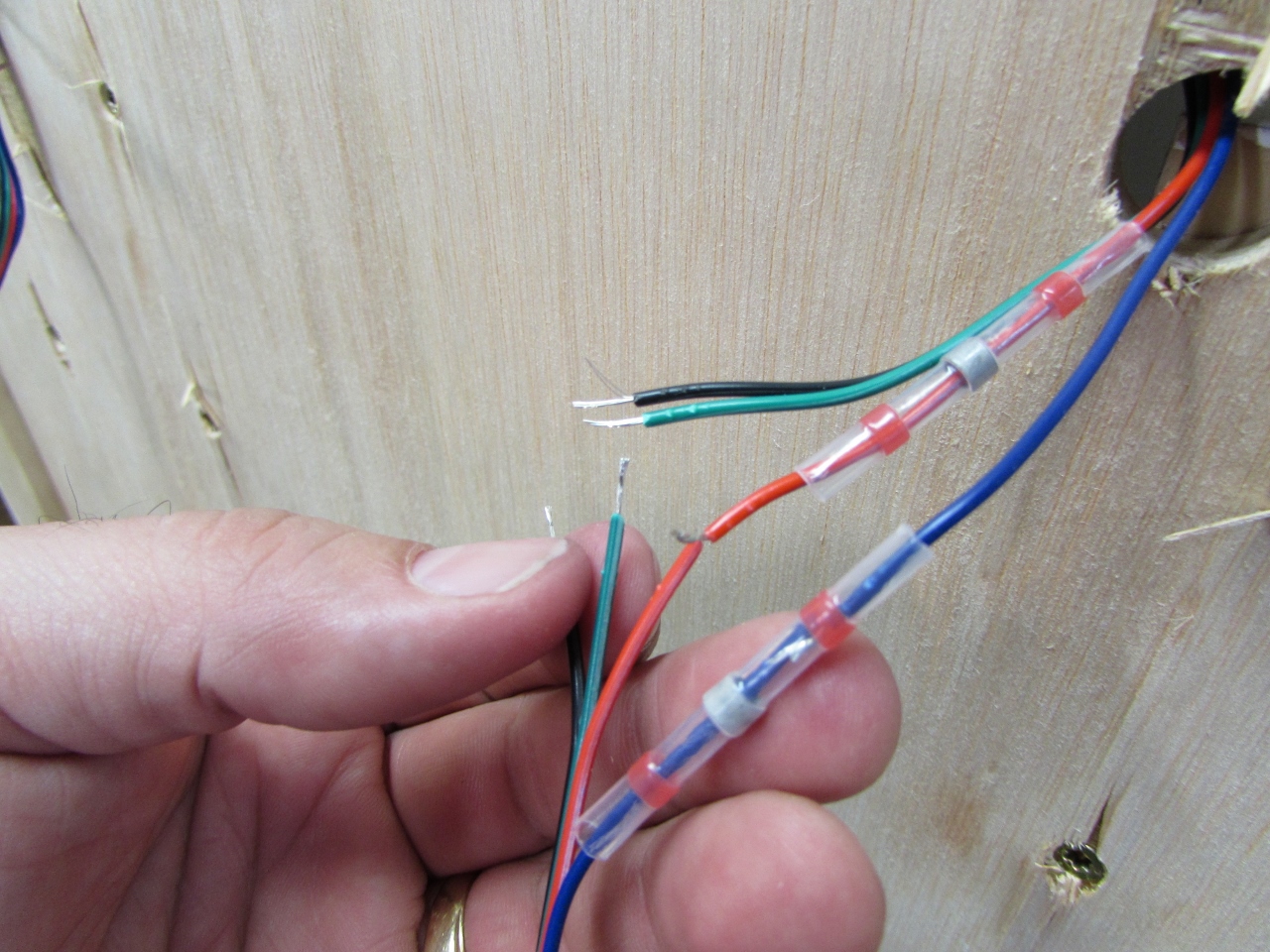
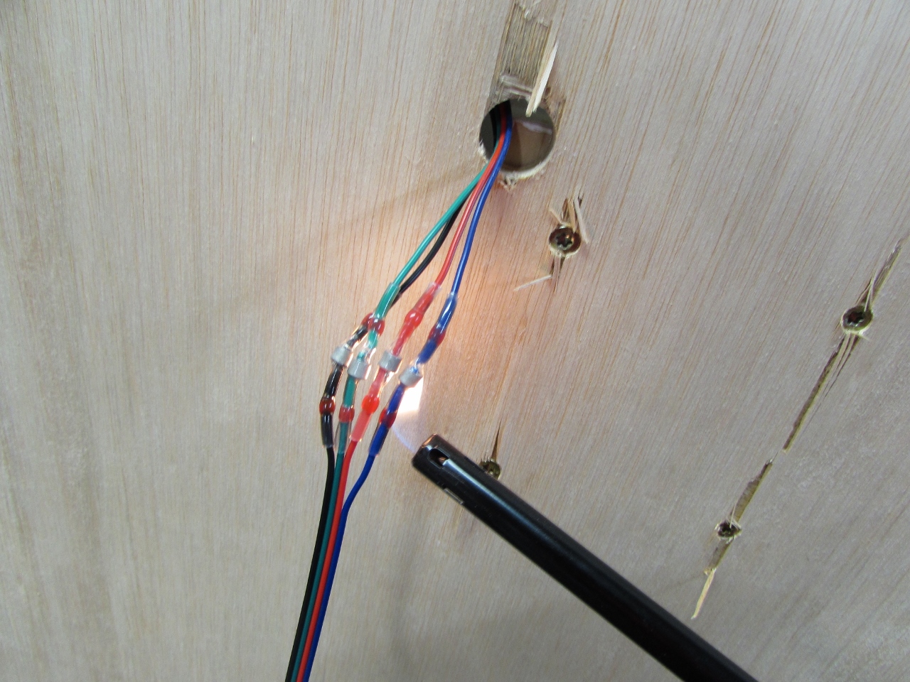
Oh well, back to the connectors. Basically you slide the connector on, twist the two wires together, then apply some heat. I used a lighter to shrink just a bit of it to hold it in place until I had all four on.
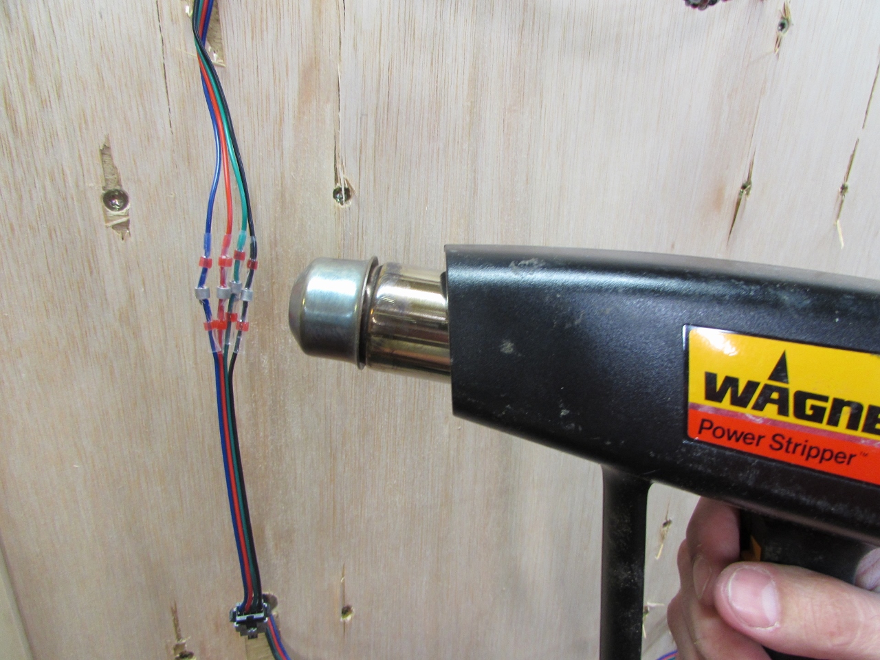
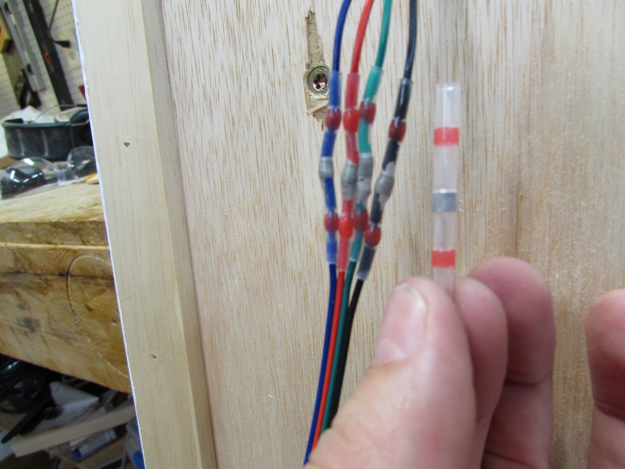
Then I set my heat gun on low (600 degrees) and shrunk it the rest of the way. In the center is a band of solder that melts onto the wires. When it is cooled, you have a permanent, water-tight connection. Awesome!
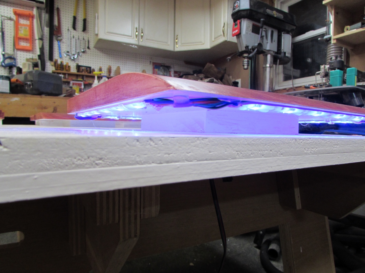
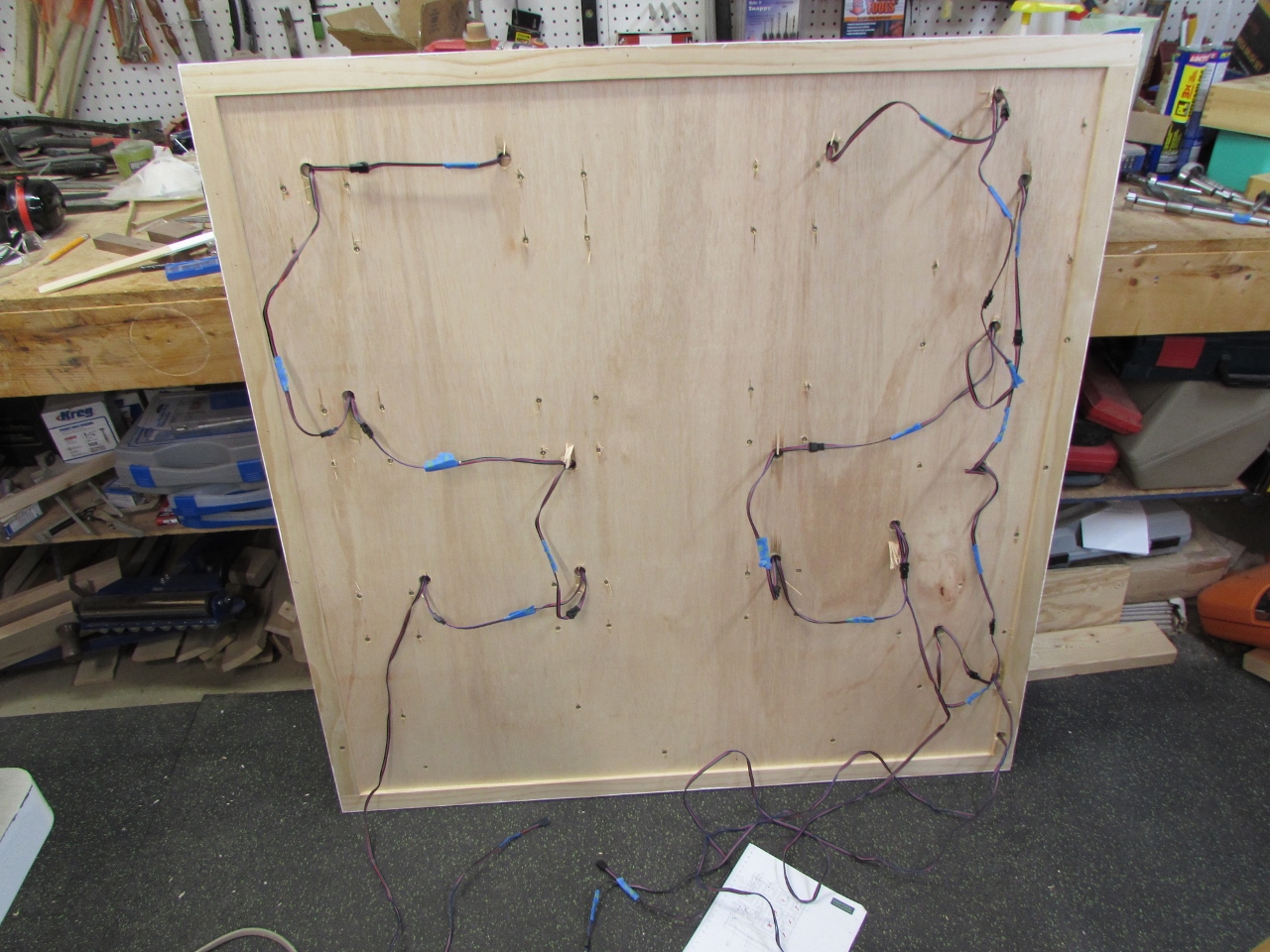
I rapidly connected together the six tiles on the right and plugged them in to test.

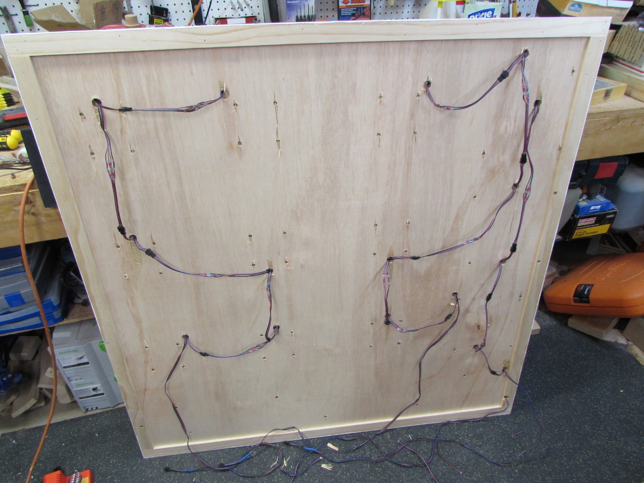
After that, it only took about a half hour to finish up all of the other extensions. Three of my long leads will go to power supply’s for the white light that outlines all of the tiles, and one of them will be going to a different power supply for the blue, inside the letters. I placed different color heat-shrink on that one so it would be easy to identify. When it was all circuited up, I plugged it in. I was so surprised when it all worked the first time. I thought for sure that I would have had at least one bad connection.
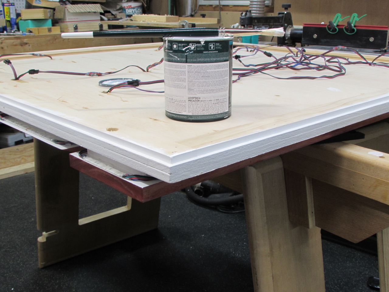
Just a few minor details left to tackle. I need to be able to route my four wire bundles out the bottom to be plugged in. I was going to chisel away a dado in the stand-off, then I realized that the connectors I was using were about 1/16″ thicker than the stand-off anyway. That is what happens when you buy them half-way through the project…
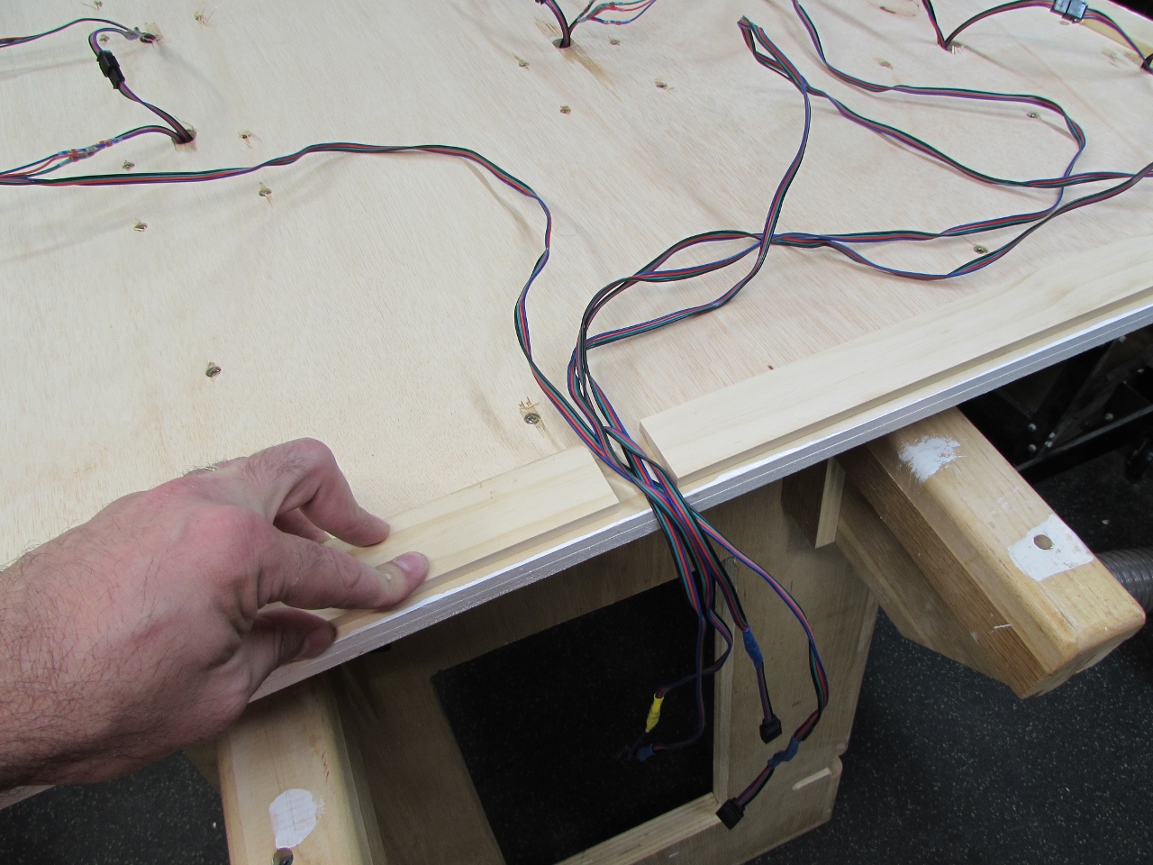
The best thing I can think to do, is add another strip to thicken the stand-off. I have just enough scrap to do it. I will just cut two pieces on the bottom leaving a 1″ channel for the wires to drop through.
I made sure to leave clearance holes for any wires or screws that went through the board below.
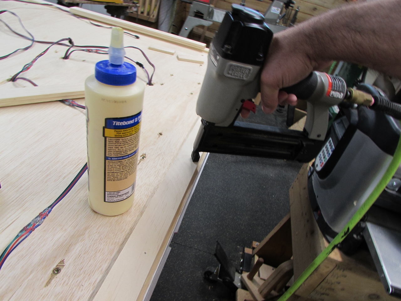
I set the new piece in 1/4″ to create a shadow line. Then I used a bit of wood glue and some 3/4″ brads to attach the strips all the way around.
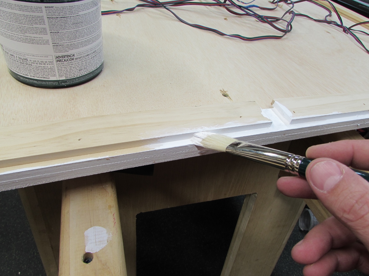
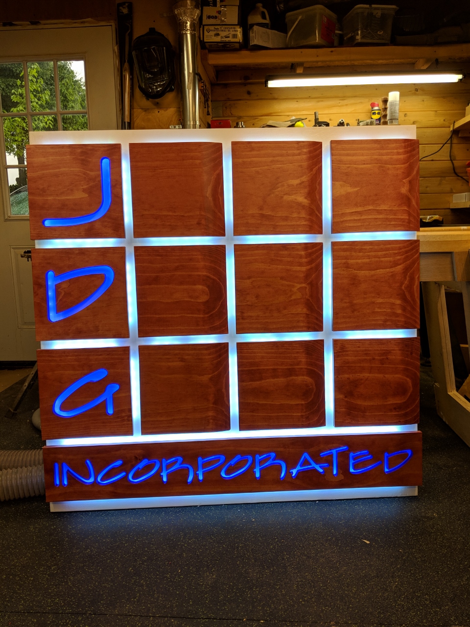
A bit of white paint and I am done.
This turned out to be a much larger project than I thought it would be. Mainly on the electronics side. I think I spent twice as much time cutting and soldering than I did woodworking. Not overly fun, but the end product is very satisfying. I will try to find time this week to get it installed at my friend’s office.
