
Laundry room cabinets – day 8
The epoxy is now dry in the knot hole. I was going to plane the excess down with a hand plane, but I discovered that my large chisel worked much more efficiently for the task. The plane removed a few thousandths at a time while the chisel took the epoxy down to the surface in just seconds.
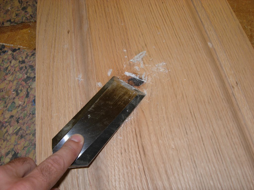
Scraping away the excess epoxy
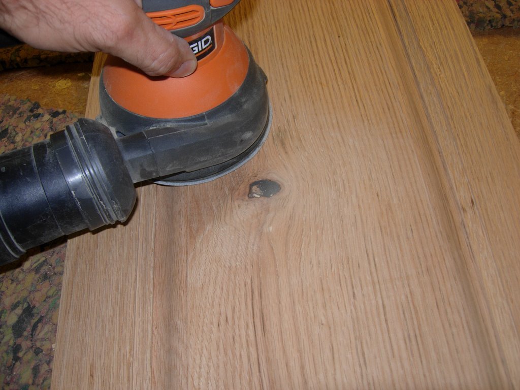
Sanding the scraped surface
I sanded down the surface of the epoxy with my orbital finish sander, then cleaned up the dust with some Naphtha. Now the surface is smooth and the knot hole completely stabilized. Since the hole is now solid, it won’t collect any dust or snag any clothes either.
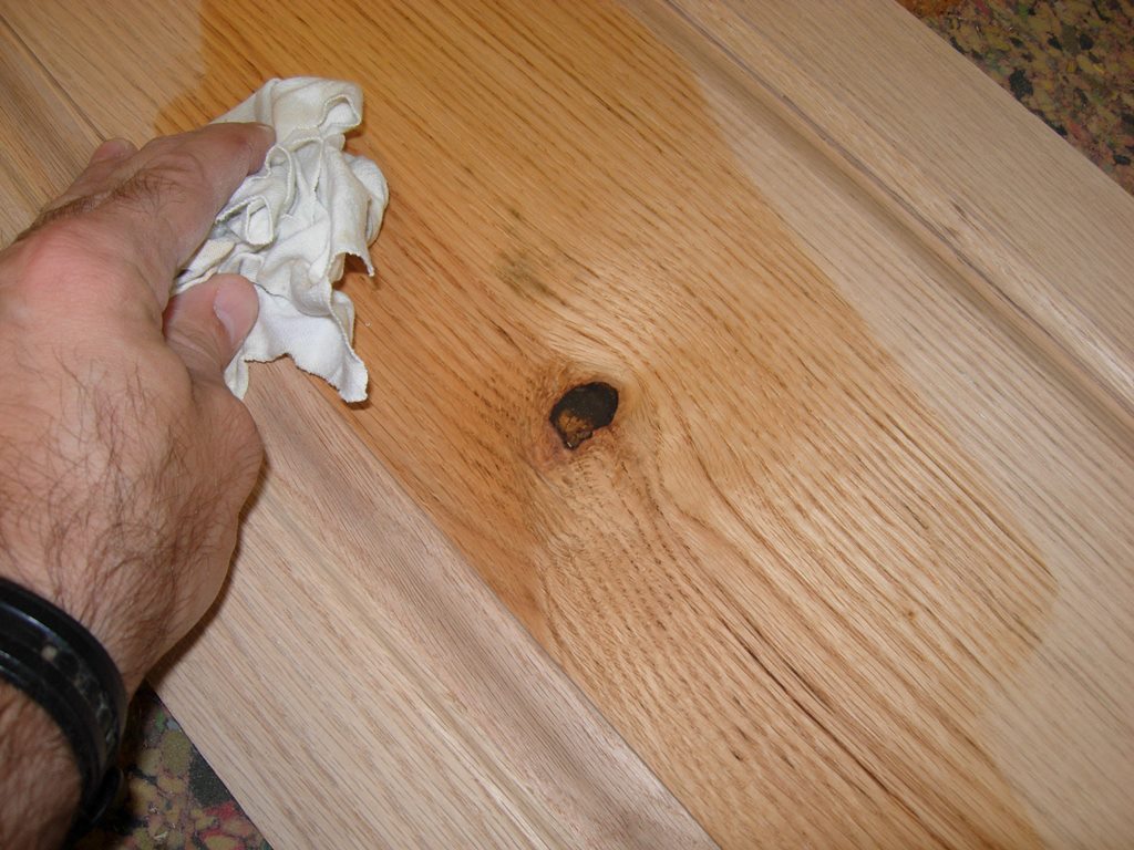
Cleans up nicely
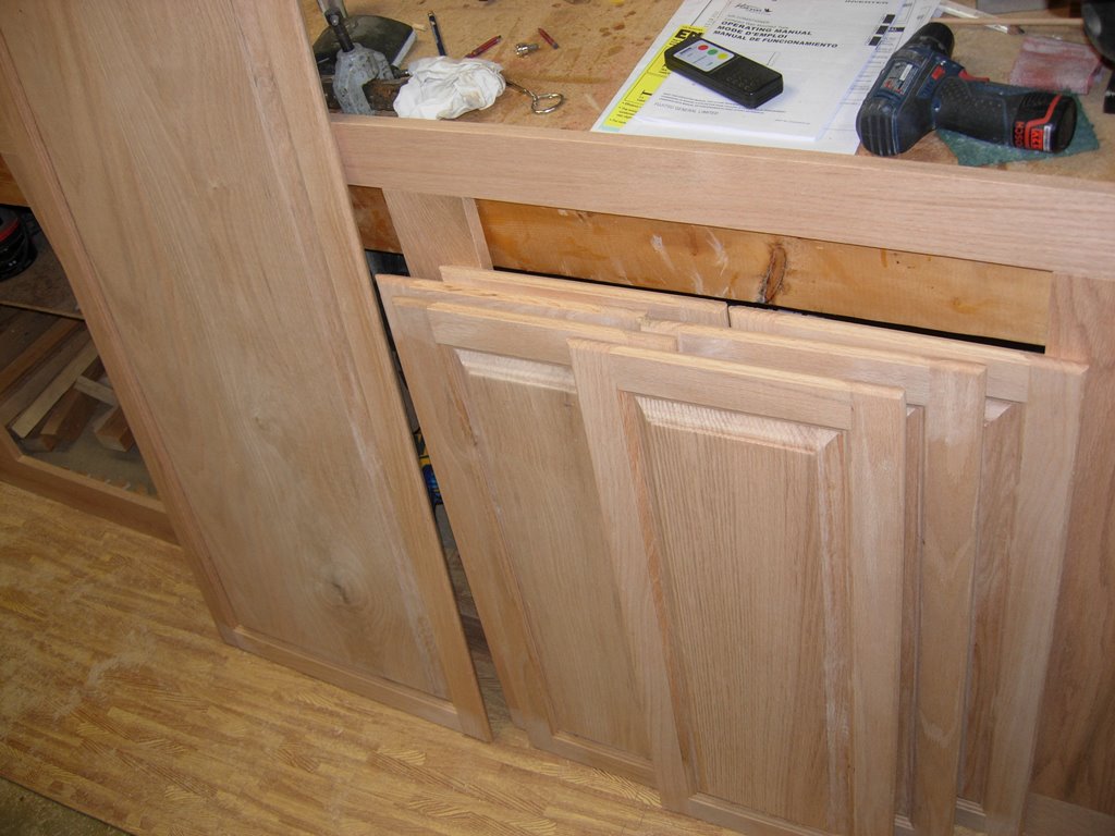
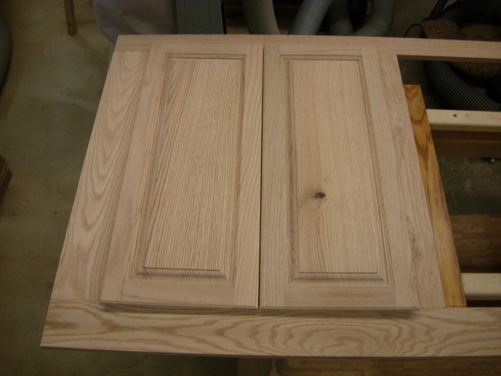
I lined up my doors to make sure everything looked correct, proportionally.
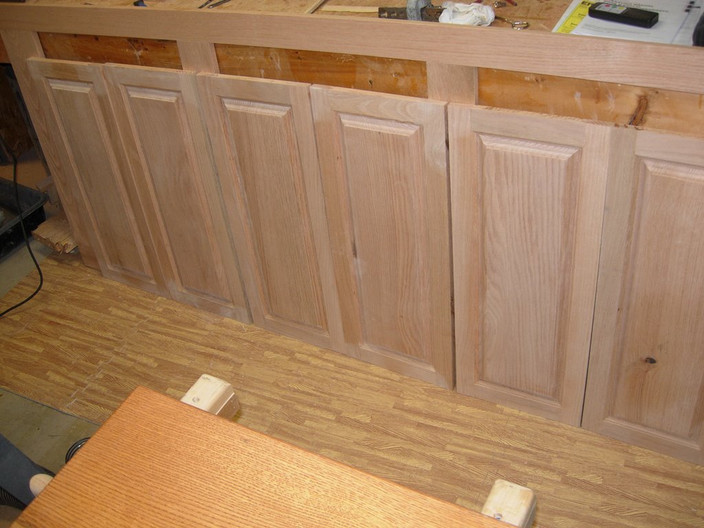
Clamps pulled and doors sanded
To soften the outer edges of the doors, I set up a door lip bit, in my router table, and ran a bead around the outside edge. This gives a nice decorative edge while also creating a lip that you can grip with your finger tips, to open the doors.
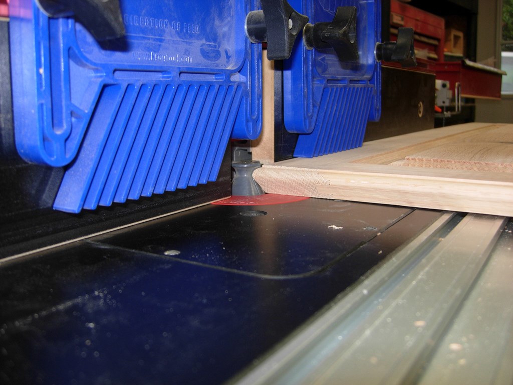
Cutting the door lip
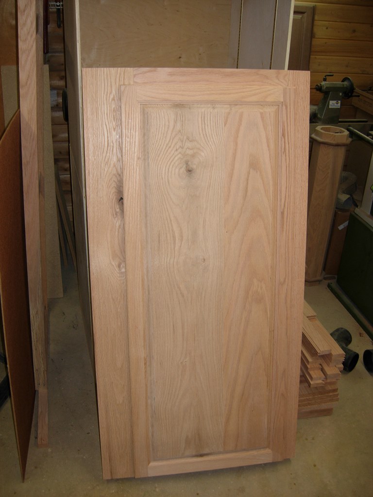
Door edges finished and ready for hinges
With the door panels complete, I have to begin figuring out how to install these european style hinges. They come with nearly useless instructions, and, of course, they are all in metric. In one instance the instructions clearly state that the hinge mount holes are to be located 7mm from the edge. This was clearly shown in a side view. Then just as clearly in the plan view, right next to the side view, it clearly states that the holes are 12.5mm from the edge. As usual, I threw away the instructions, and proceeded to create a mock-up and try multiple iterations until I hit upon the one that gave me the desired results.

Testing hinge installation
Unlike regular hinges where you attach them to the door, then line everything up, then attach to the frame. These hinges need to be pre-drilled and located before you attach the hinges. There is a minimal adjustment available in each hinge, but it doesn’t always help when you have more than one hinge on a side. My large, lower door will have four in a row. Having one of them off will bind the whole door. Since I can now pull dimensions from my mock-up, I need a way to keep the holes all lined up as perfectly as possible.

Building a quick drill press table
The best way that I could think of, was to have a large drill press table with an adjustable fence. I was eyeing them up online. They range anywhere from $50 to $200 depending on what options you want. My primary need was a large table with an adjustable fence. Since it would take a week to order the one I wanted, I decided to throw something together with scraps from around the shop. I cut a piece of 3/4″ plywood down to 28″x18″, then located it centered on the drill press table and traced the table location. I drilled and counterbored two holes, for carriage bolts, that fell within the slots on the drill press table. I can add more later, but I only have two bolts lying around, so two it is. My featherboards, for the router table, had some extra threaded rods with knobs. These are for when you need to stack two featherboards together. Since I rarely do, I re-purposed them as adjustment knobs for my fence. They came with T-nuts for use in standard T-tracks . I decided to utilize them so tightening the knobs would only be a one-handed operation. I clamped a straight-edge along the side of the table and cut a 1/4″ groove through the plywood, stopping about 2″ from each end. Next, I used a 1/2″ straight bit to counterbore the groove, giving the T-nuts a slot to ride in that would loosely hold the nuts in line, so they could be tightened “hands-free”. Next I simply cut a 1-1/4″ square piece of oak for my fence and drilled two clearance holes for the threaded knobs. For 20 minutes of work, the new table and fence work surprisingly well. I will have to contrive a way to add adjustable stops, in the future, but for now, this will do exactly what I need.

Table completed
I found a U-shaped jig, that I used a drill guide, on a previous project. It worked perfectly as a stop that I clamped into place, 3″ away from the center of the drill bit. This allowed me to locate every single hole, exactly 3″ in from the end of each door. I located the 35mm forstner bit, the required distance from the fence, and drilled all of my pockets on the left side of the panels.

Drilling out the 35mm hinge hole
I repeated the process on the other end of the doors, then carefully measured and located the middle holes on the larger, lower door.

Hinge pockets drilled

Locating holes for mounting screws
Instead of making a template, I used my mock-up as a locator for the mounting holes, for the hinges. I merely held it parallel to the edge of the door and scribed the holes with a pencil, then drilled all of the pilot holes on the drill press. These I could have drilled by hand, but I had this new drill press table…
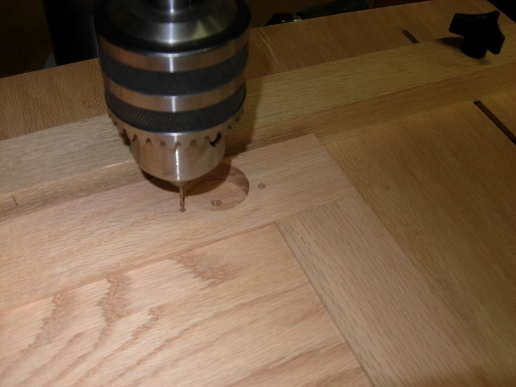
Drilling mounting holes on the drill press
Locating hinge mount on face frame
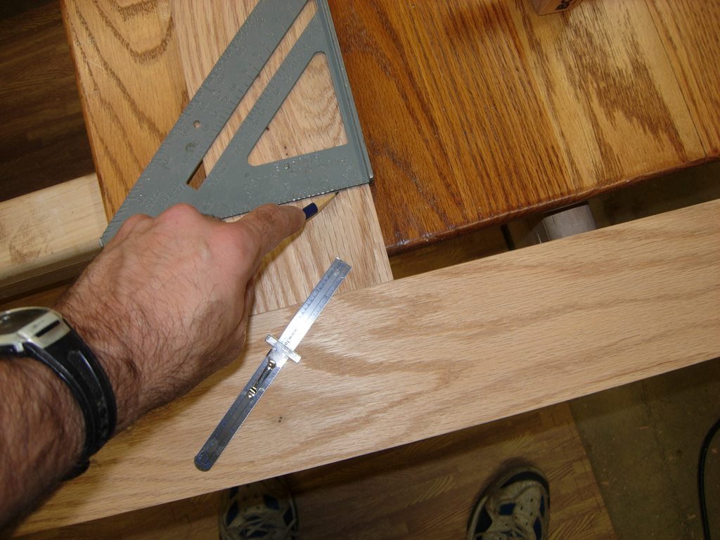
The next part was a little more tedious. I drew a line 2-1/2″ off of the top and bottom of the face frame, to locate the center of the hinge mounting plate.

Setting the distance from the edge with a marking gauge
I scribed a line with my marking gauge to locate the distance from the inside edge of each door opening. Then laying each mounting plate over these carefully laid out lines, I located the center of each mounting slot. Next I drilled a small pilot hole in each slot location.

Drilling the pilot holes for the hinge mount
I installed the first set of hinges. The slot in the mounting plate allows about 1/8″ of adjustability, up and down. I centered the door vertically, then tightened the screws.

First door installed
First set lines up perfectly
With only slight adjustments, The doors were lined up with each other. I was truly surprised that the hinges weren’t more frustrating than they were. All the careful measuring and preparation paid off, and the doors look pretty good.
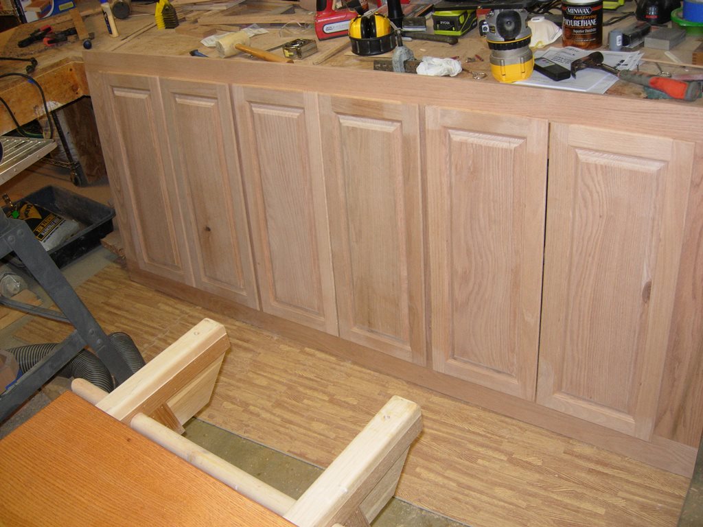
Upper doors installed
I also was able to measure and install the four hinges for the larger, lower door without much trouble. It is heavy, but it swings smoothly.
Lower door mounted
Well, it is nearly midnight again. Everything is just about ready for finishing, just a few finishing touches with the sand paper. The only thing left is a shelf for each of the cabinets. I had nearly forgotten about them. I will be making them out of 3/4″ plywood with a nice piece of oak edge banding. It shouldn’t take long so maybe I will be spraying on the finish by this weekend.
