
Adding a digital readout to my Jet 15″ planer
For Christmas, my lovely wife gave me a remote digital planer readout for my new planer, to make it easier for me to see what board thickness I am planing to.

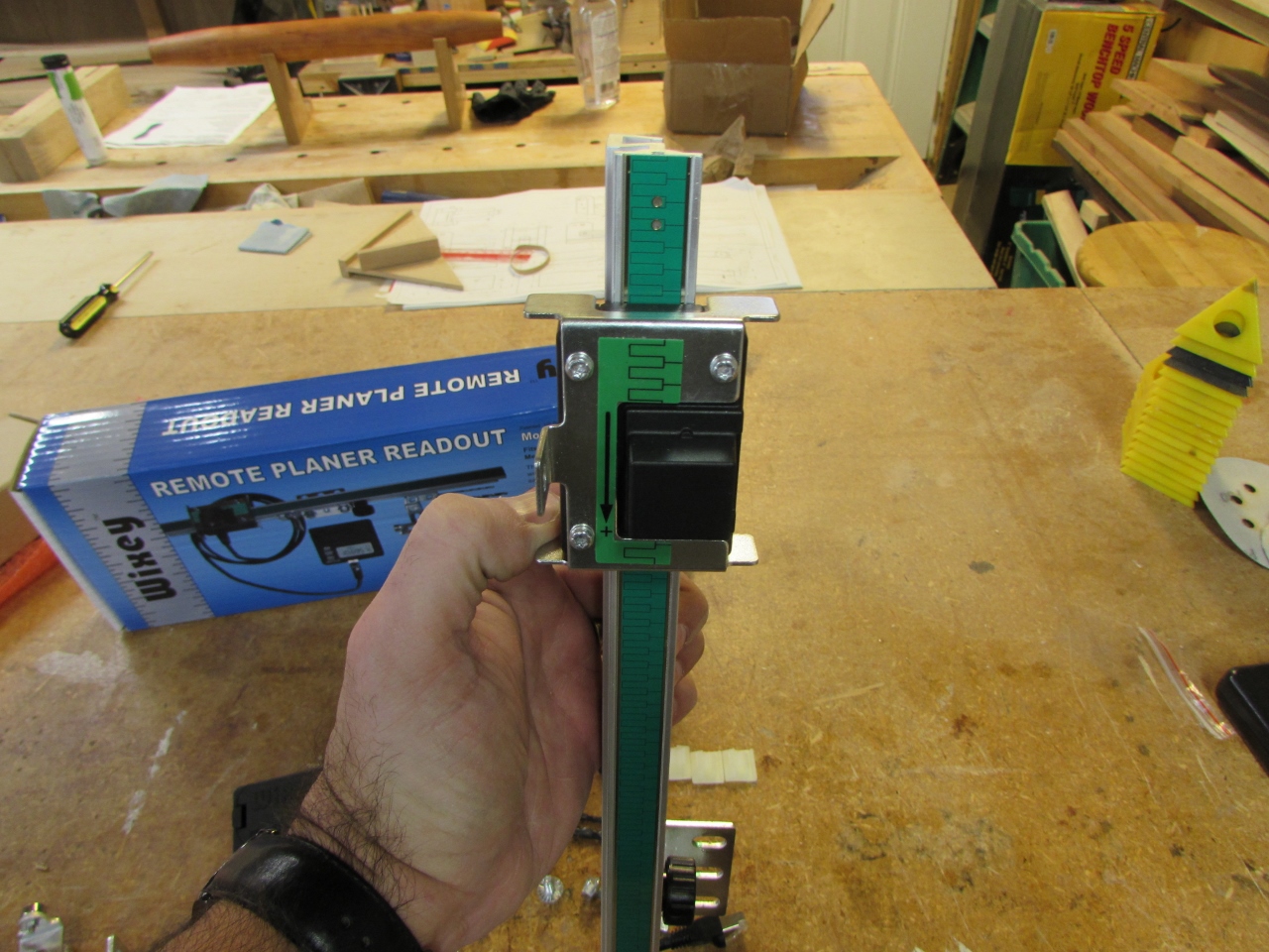
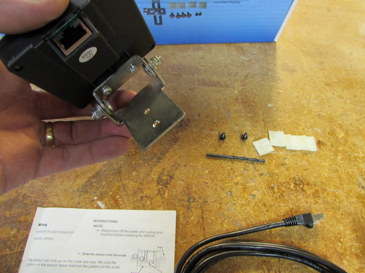
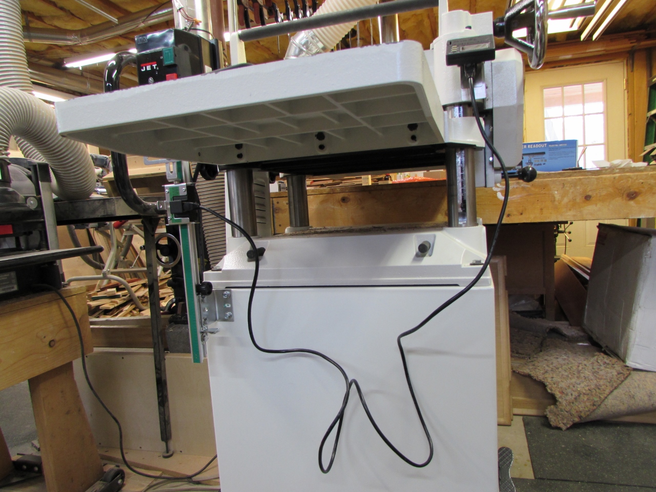
The readout is a Wixey model WR550. This one is nice because the digital readout can be remotely located allowing the sensor and scale to be mounted out of the way. The next model down, the WR510 has the readout mounted to the scale, requiring it to be located where it is easy to see, but that means the scale sticks up where you could potentially hit it with the board you are planing.
I found the instructions to be less than helpful. There were lots of pictures of mounting options, but no detailed description of how it worked. This made it difficult to decide on a mounting location. After watching a YouTube video of a gentleman installing one on a Grizzly planer, I abandoned the directions altogether.
The installation was pretty straight forward. The first step was to find a location where all the brackets could attach that left the scale bar out of the way. Since I do all of my work on the right side of the planer, I decided to mount it on the left. I would have mounted it on the rear, but it was inaccessible at the moment and I didn’t have a big, strong helper to lift this 500 pound plane to better location for installation. As it is, the front, left side is usually completely out of the way of any large objects that could knock it around.
I did have to drill into my pretty, new planer for this installation. I opened up the access panel in the rear of my planer to make sure there was nothing in the way of drilling into the base cabinet.

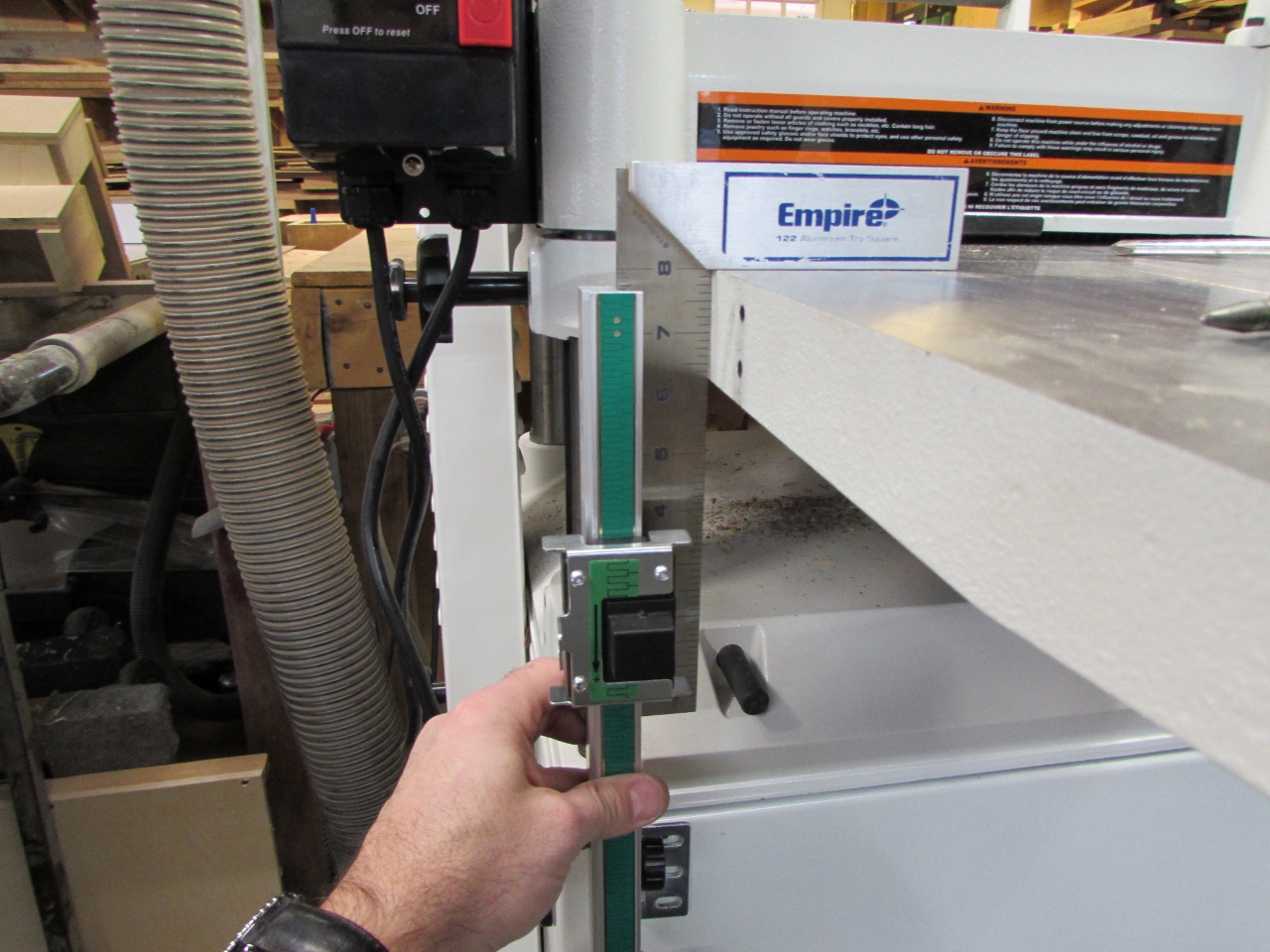
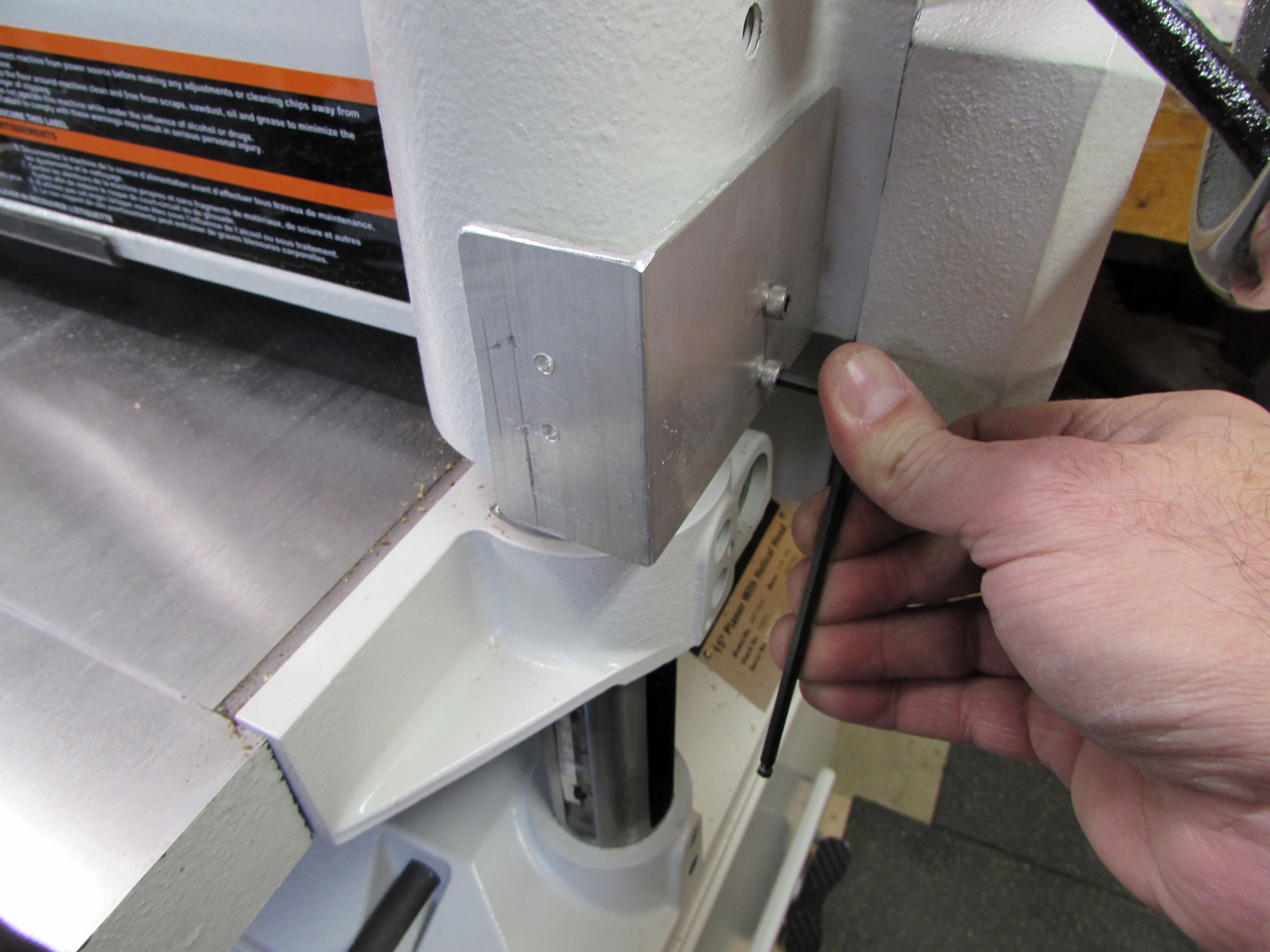
Using a square to make sure the scale was perpendicular to the infeed table, I marked the mounting hole locations.

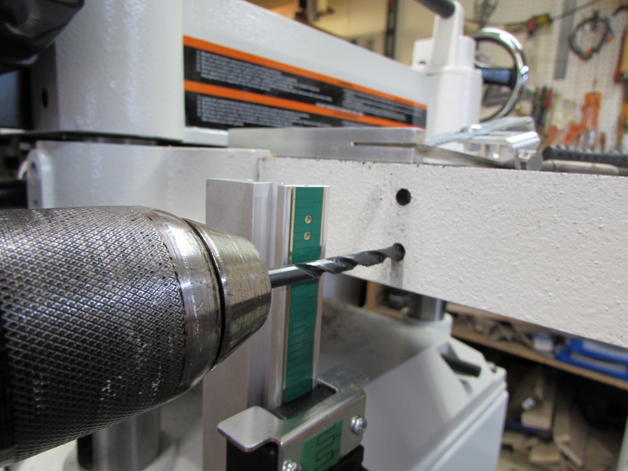
I drilled out the two required holes with the supplied 5.5mm drill bit, then inserted the mounting screws, making sure the scale stayed lined up with the square.

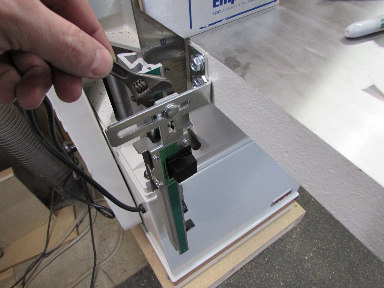
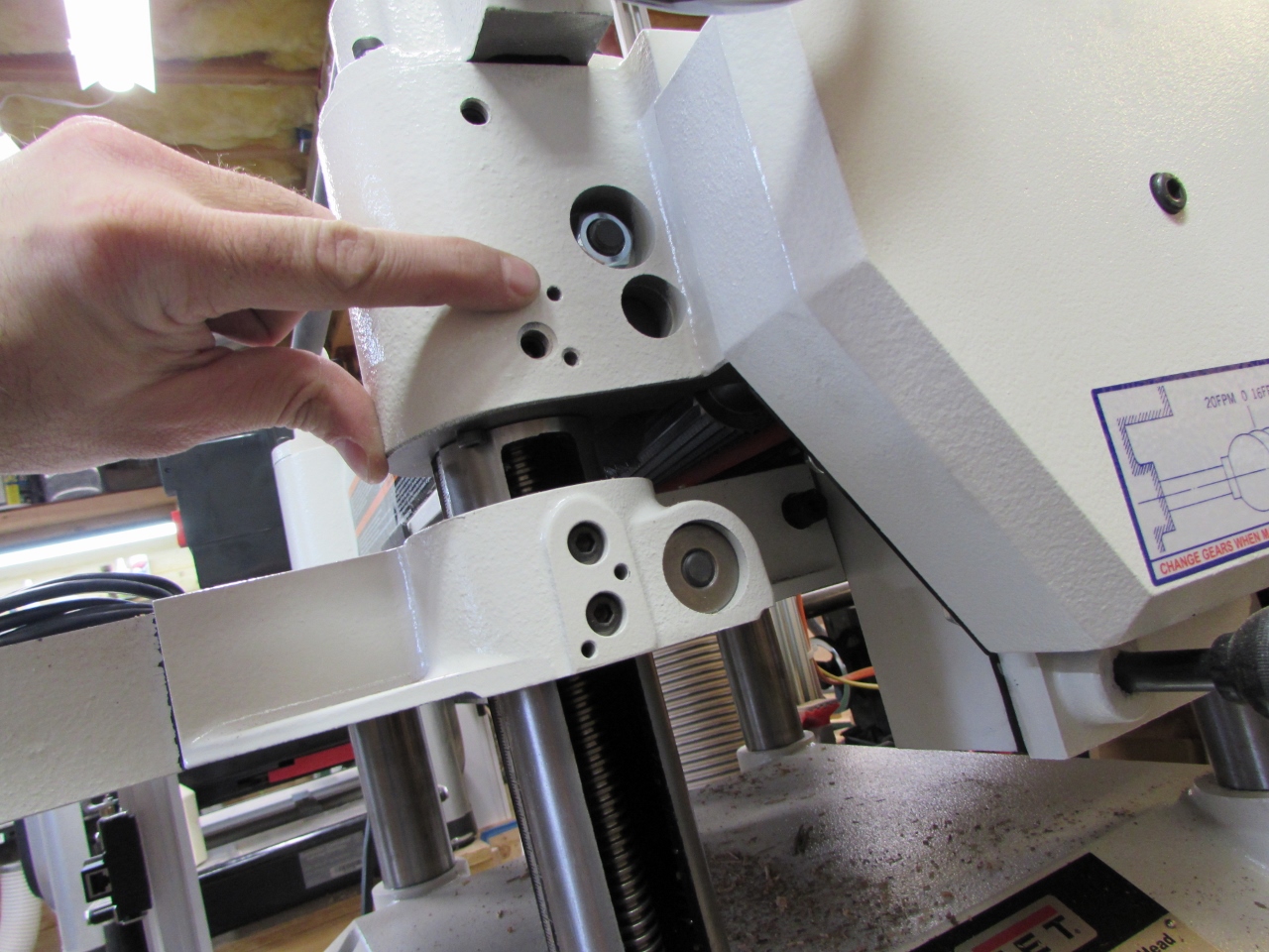
I repeated the process with the magnetic arm that attached to the sensor.

I marked and drilled the hole locations into the cast iron table. This took a lot longer because the cast iron table was much thicker than the sheet metal cabinet. I made sure to put oil on the drill bit, as I drilled, to keep from over-heating the drill bit. Over-heating could ruin the temper of the bit, causing it to dull quickly and not hold a sharp edge if sharpened again.
I also added a drop of oil to the self-tapping screws as they were installed to make the tapping process go a bit easier.

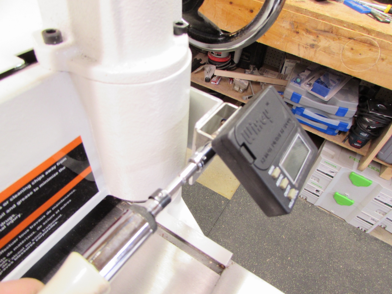
Once installed, I adjusted the magnetic arm to sit squarely on the middle of the sensor.

The scale is installed, now on to the remote readout.

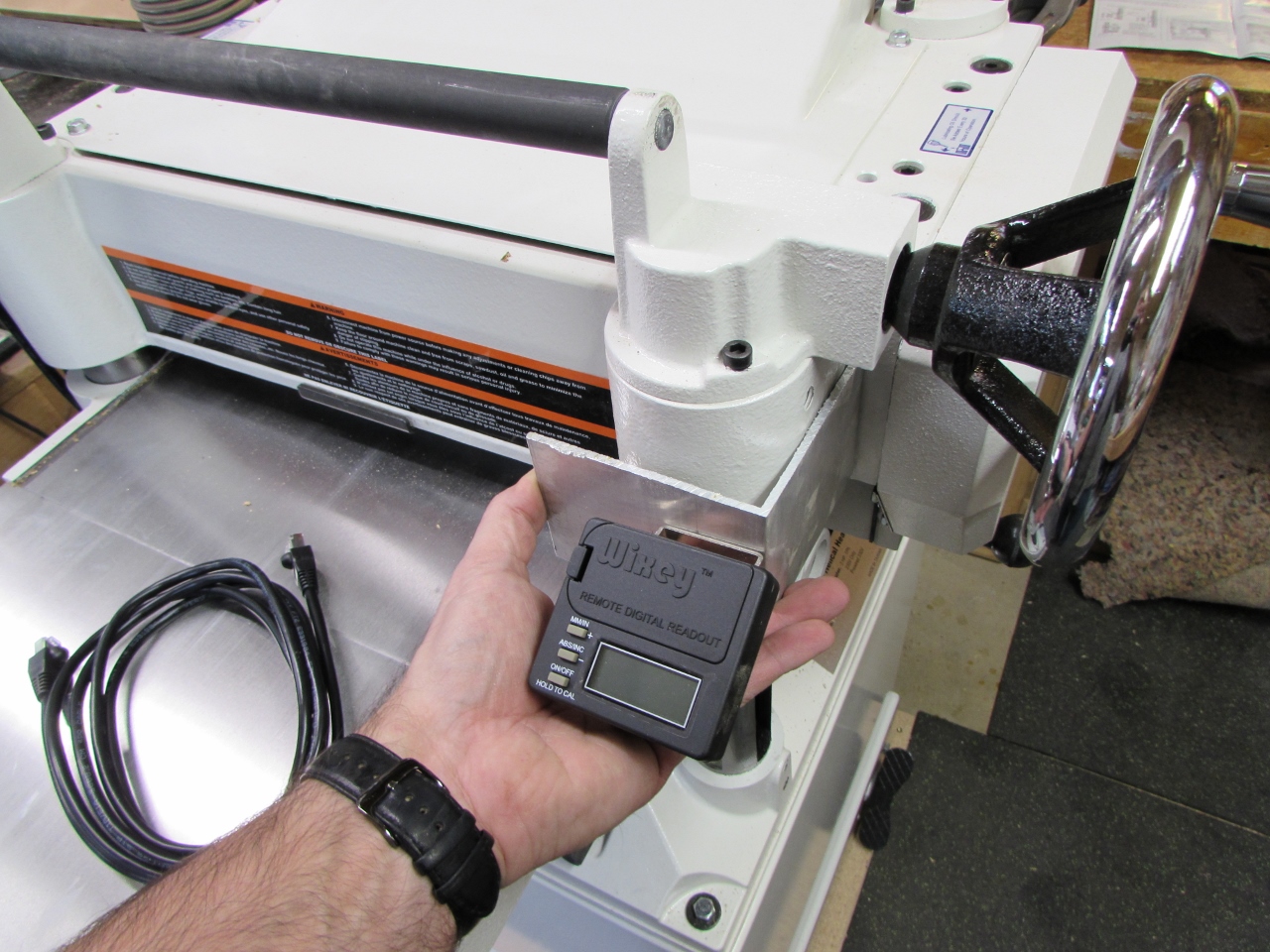
The readout has an adjustable base that just needs to be screwed somewhere you can see it.
I believe you could use some good double-sided tape if you wanted, but I decided to repurpose some existing mounting holes, on the right side of the planer. I think they were for Jet’s digital readout, but for twice the money, their readout seemed to have far worse reviews.

I located some screws that would fit into the existing holes then rooted through my metal scraps until I found a small piece of aluminum angle.
The 4″ length was perfect, but the width had to be cut down.
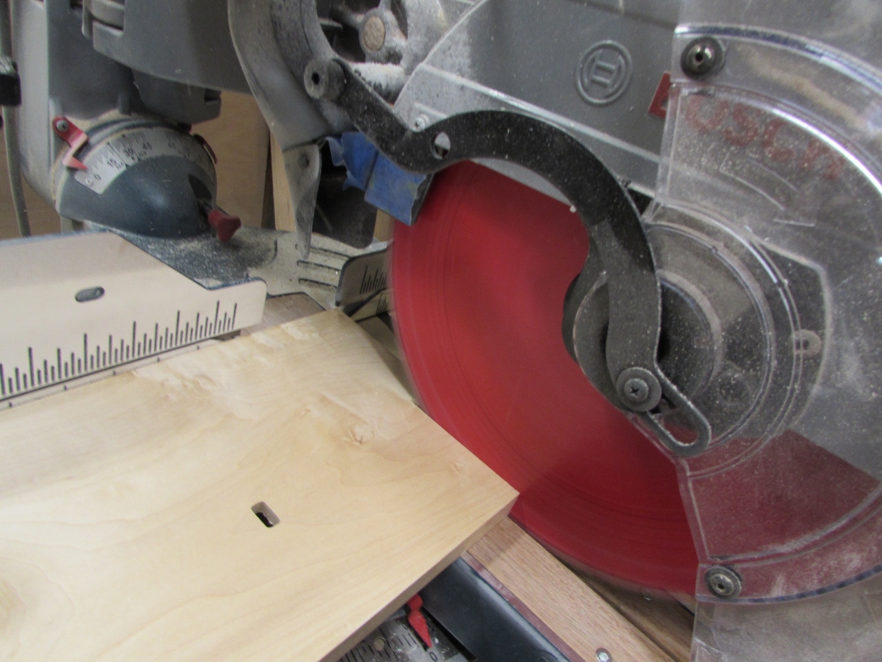
I marked the width, then set up a sacrificial fence on my miter saw to make cutting the angle safer.
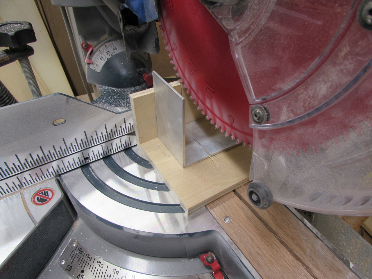
Cutting aluminum is fine on the miter saw as long as you take your time and wear your safety glasses.


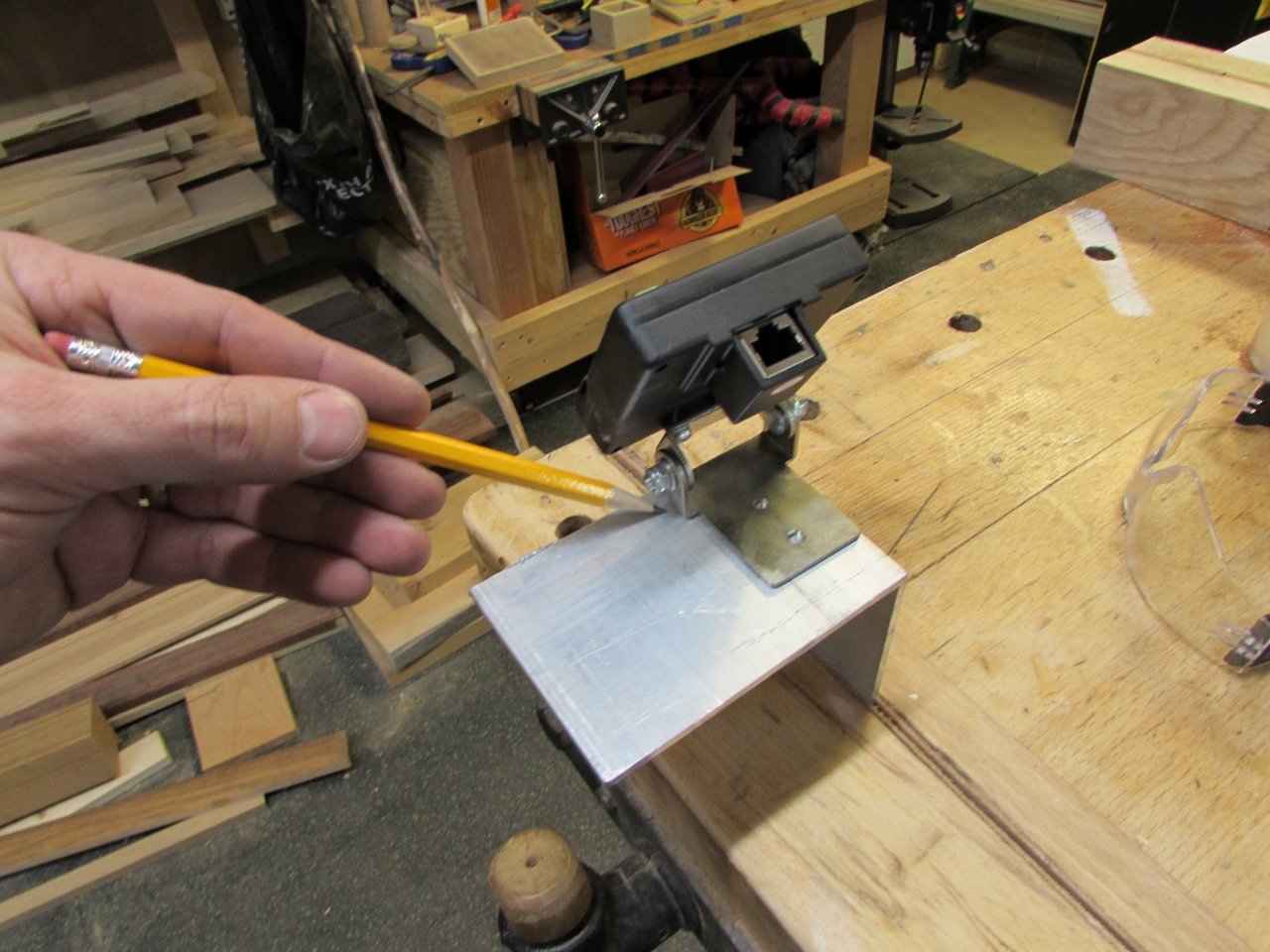
Next, I marked and drilled out my mounting holes, then used a mill file to smooth all the edges and round over the corners.


I attached the bracket with (2) 3/4″ long #10-32 screws.

Then I attached the readout with the screws supplied, and tightened the pivot screws.
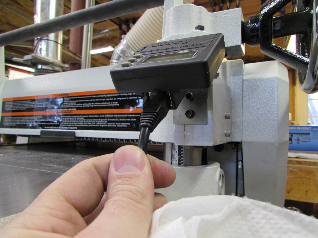
A wire plugs into the sensor, connecting it to the readout.
I cleaned the surface of the cabinet below, using denatured alcohol.
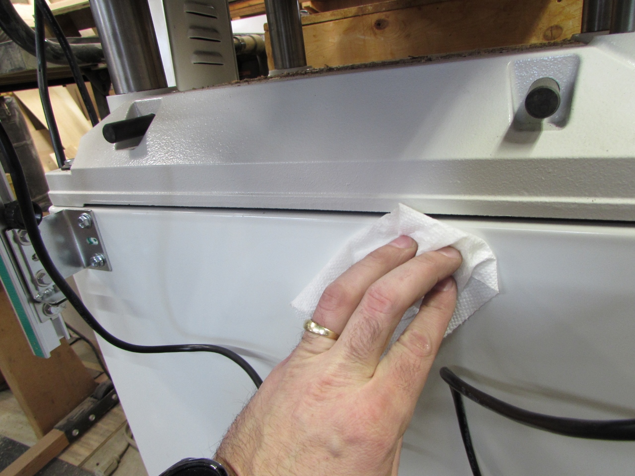
Then I attached the wire holders that were included, using double-sided tape. I arranged the wires so there was just enough slack to follow the moving table.

Now it was time to calibrate the readout.

I started by planing down a scrap piece of wood, then cutting off the snipe and removing a small chunk.
The chunk was placed between the jaws at the bottom of the sensor, and the readout was zeroed out.

When the chunk was removed and the jaws closed again, the readout matched the thickness of my planed board.

I ran the board through for another pass, and it was dead on. Installation complete. I also checked to see if it remained accurate after the digital readout was turned off. I turned it off and moved the table. When it was turned on again, the same number appeared for a brief moment, then it jumped to the new location. Perfect!

A couple of other features that were of interest:
-You can switch between inches and millimeters.
-On inches, it will display the closest fraction, when it is within +/-.002″ of the fraction.
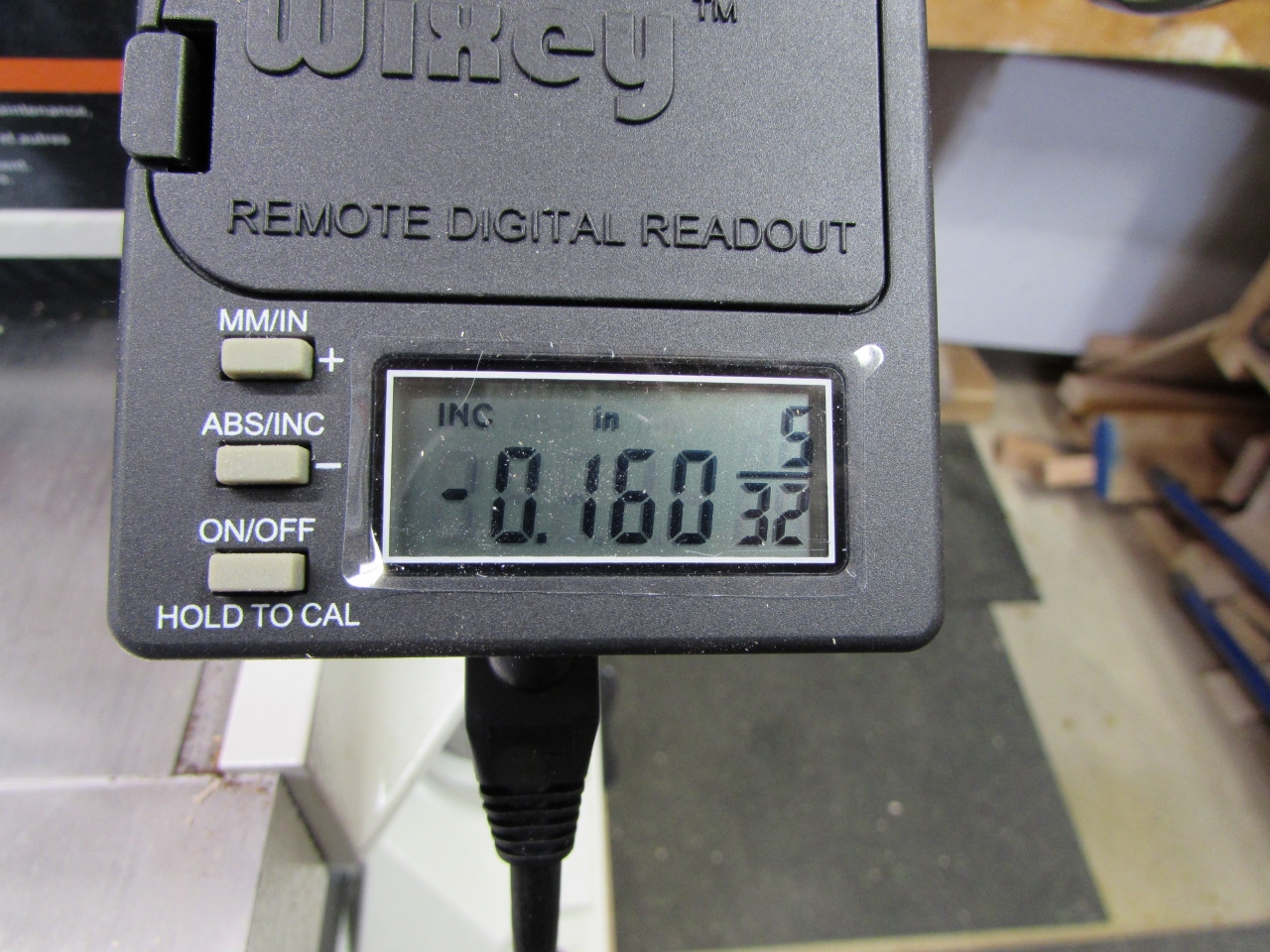
-You can leave it in “Absolute” mode, like I was using for the calibration, or you can switch to “Incremental” mode where it will zero out and you can subtract from your current thickness, like it shows in the picture below.
The readout runs on (2) AAA batteries and Wixey claims it will last for two years. There is also an “Auto shut-off” for those of us who will never remember such things…
