
Bathroom Vanity – day 1
Wow, October has not been the best month for productivity! Honestly, I wish I could hit the “UNDO” button and try October again. Between septic problems, car problems, several household appliances breaking, and my dad going into the hospital for a week, it has been an expensive, frustrating month. I have barely had a chance to get into the shop. Heck, for a couple of weeks there, I was afraid something else would break if I even walked in there.
Being an optimist (most of the time) I decided to start November with a new, big project. My friend Charlie asked me to make him, and his wife, a vanity for their new bathroom. They haven’t quite been able to find the features they like in a cabinet that is the size they need. This one will be 54″ wide, and an inch or two shorter than normal, with lots of big drawers, and a cabinet in the center. And it is up on turned feet. Here are the plans for the design that I came up with: 54wide x 33tall-vanity.PDF
They will have a granite counter top made for the vanity, so I decided to build the main carcass out of 3/4″ thick cabinet grade plywood. The door, drawers, and drawer fronts will be made with poplar. The cabinet will be painted, so I don’t need to worry about the wood grain matching. All of the main carcass pieces will come from one sheet of 3/4″ plywood, and the rear panel will be 1/2″ thick, so that will come from a second sheet of plywood. While I was buying plywood, I picked up a nice piece of 1/4″ thick, paint grade plywood for the drawer bottoms.
I bought 18″ full extension, soft closing drawer slides from Lee Valley. I also purchased the turned feet from Amazon.com . I could have turned them on the lathe, but I kind of wanted them all to match…

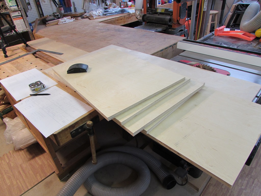
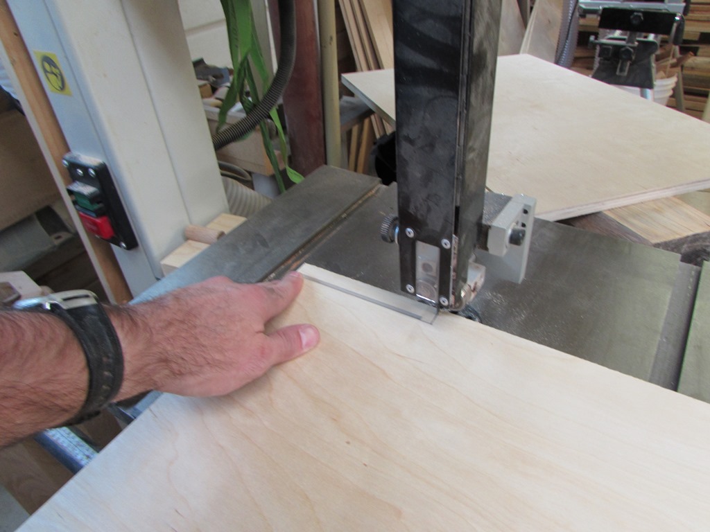
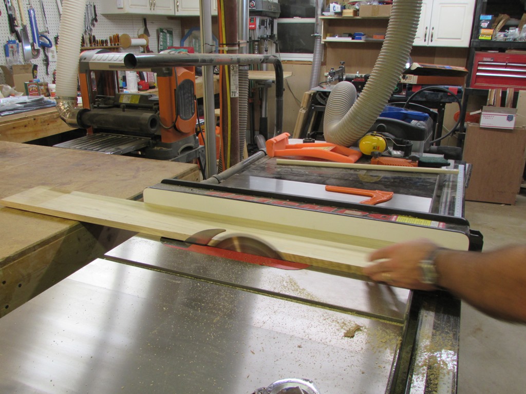
I decided to start with the most awkward part first. Breaking down 3/4″ plywood is not fun, and it is heavy. My only local source for cabinet grade plywood usually manages to only have plywood that is not square. This has caused me problems in the past, so The first thing that I do is check for square. Sure enough, this sheet is out by a 1/4″ over the 4′ width.
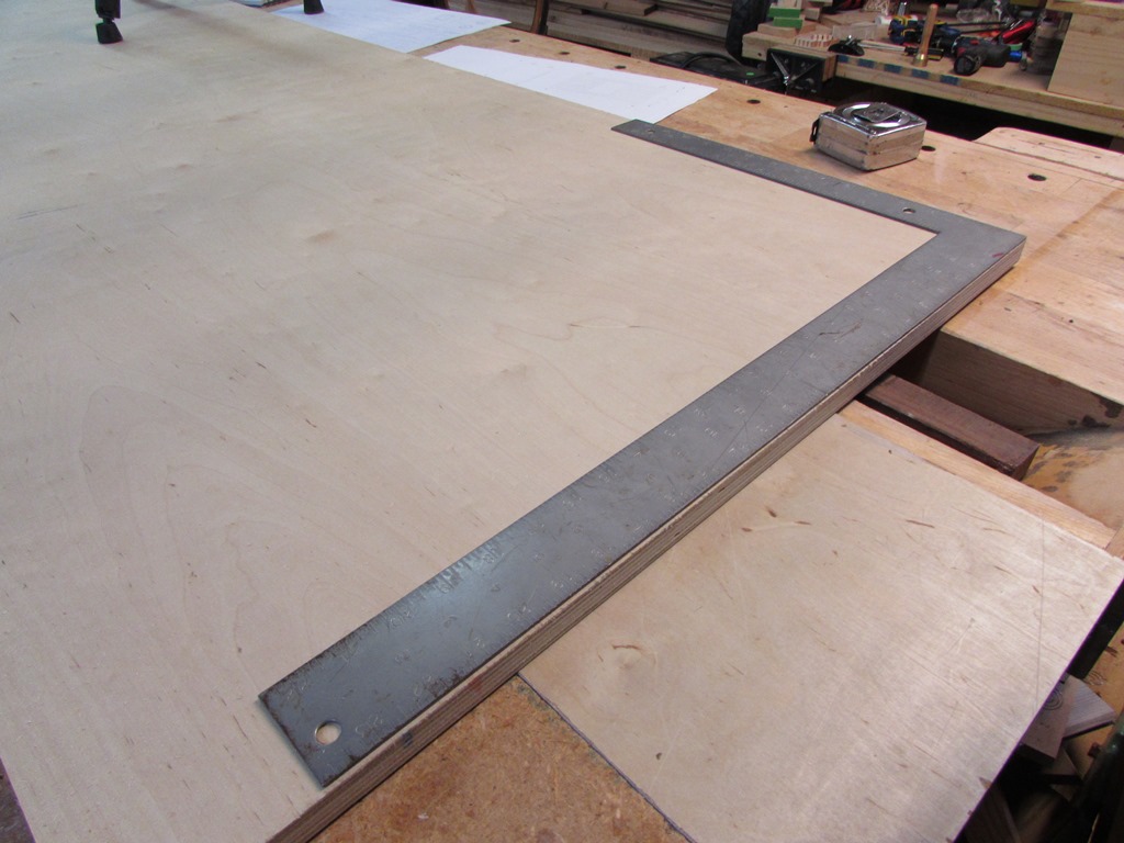
After I cut the full sheet, roughly in half, I set up my track saw, against a framing square to square up the ends, as well as cutting each side piece to length. I have done this with just a regular circular saw as well. You just clamp a straight edge in place and cut along it.

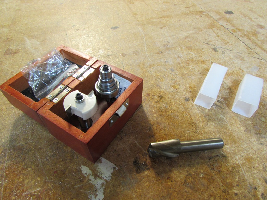
Once the sheets were all broken down, and ripped to their proper width, I got out some new router bits that I bought for this project. On the right is a 3/4″ spiral bit for cutting the dados that will capture the center vertical panels. On the left is a rabbeting kit. You can change out the bearings to give you different, accurate rabbets.

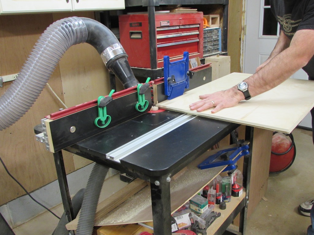
I carefully reviewed the plans and marked the edges of the plywood that needed rabbets. Next I set up the bit for cutting 1/2″ wide rabbets and set the depth for 3/8″. I did a couple of test cuts to make sure I could create a clean rabbet with just one pass on the router table.

After tweaking the depth a bit, I cut the 1/2″ rabbets.
Locking the bit in place with a block of wood, I swapped out the bearing to create a 3/8″ width rabbet. By leaving the bit in place, I maintain the exact same 3/8″ depth.


I ran the 3/8″ rabbets, then did a test fit. Fits up pretty good.

The next step was to lay out the 3/4″ dados in the middle of the bottom board.

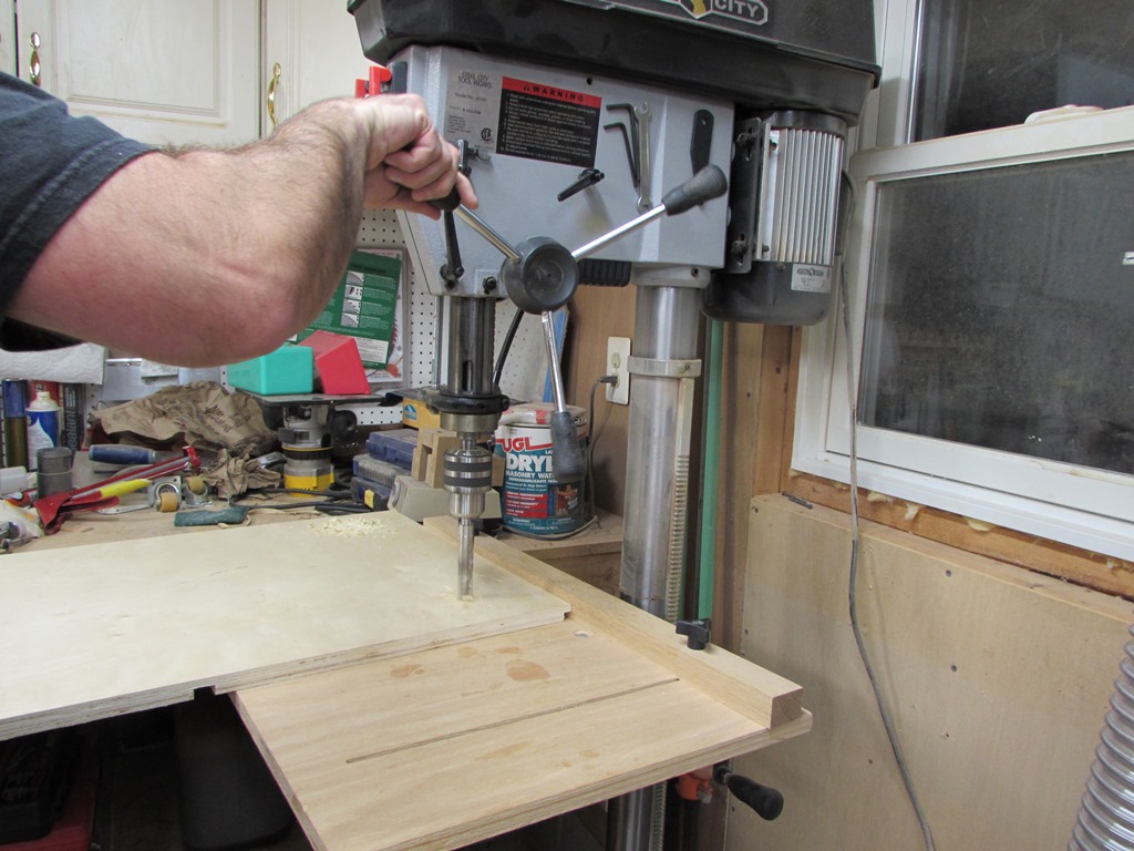
After installing the 3/4″ spiral bit, I measured to the edge of the base, and clamped a straight edge in place to act as a guide for cutting.

I lined my dust collection hose up behind the router and cut my first dado, holding tightly to the straight edge.


Test fit was perfect, so I cut the second groove in the same fashion.

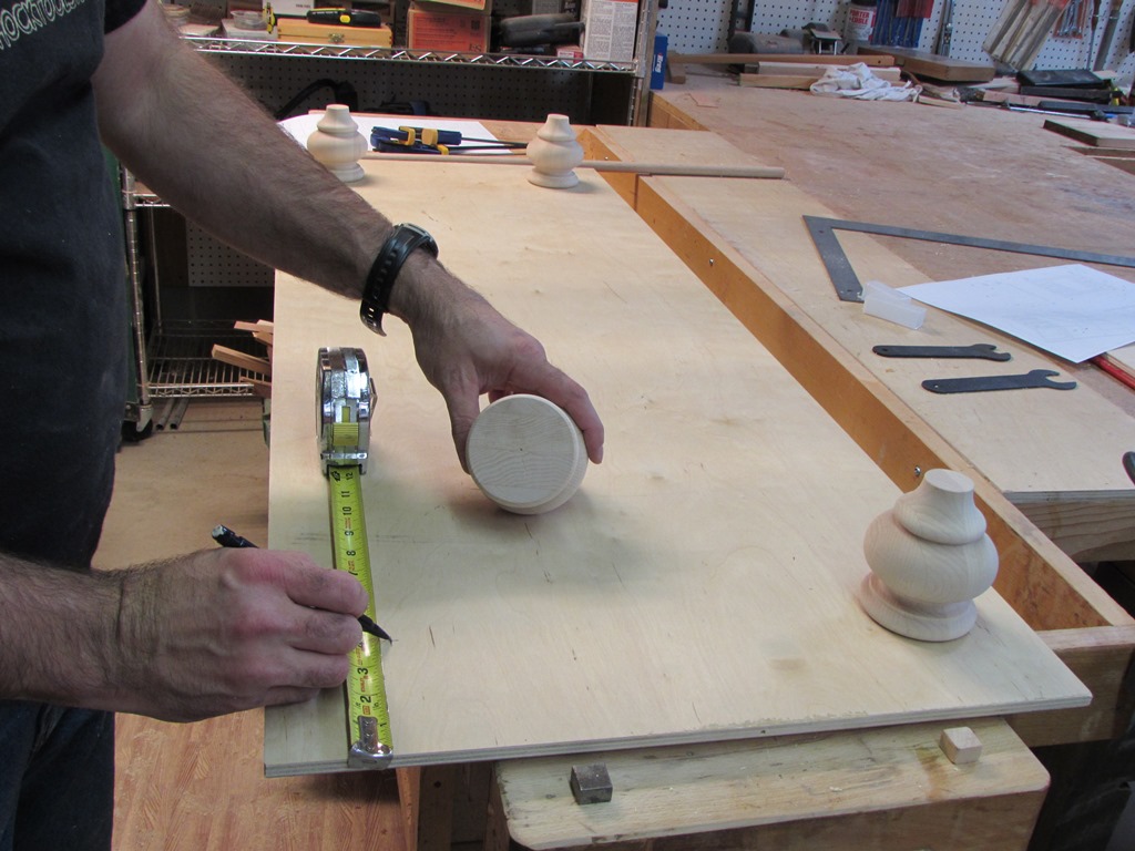
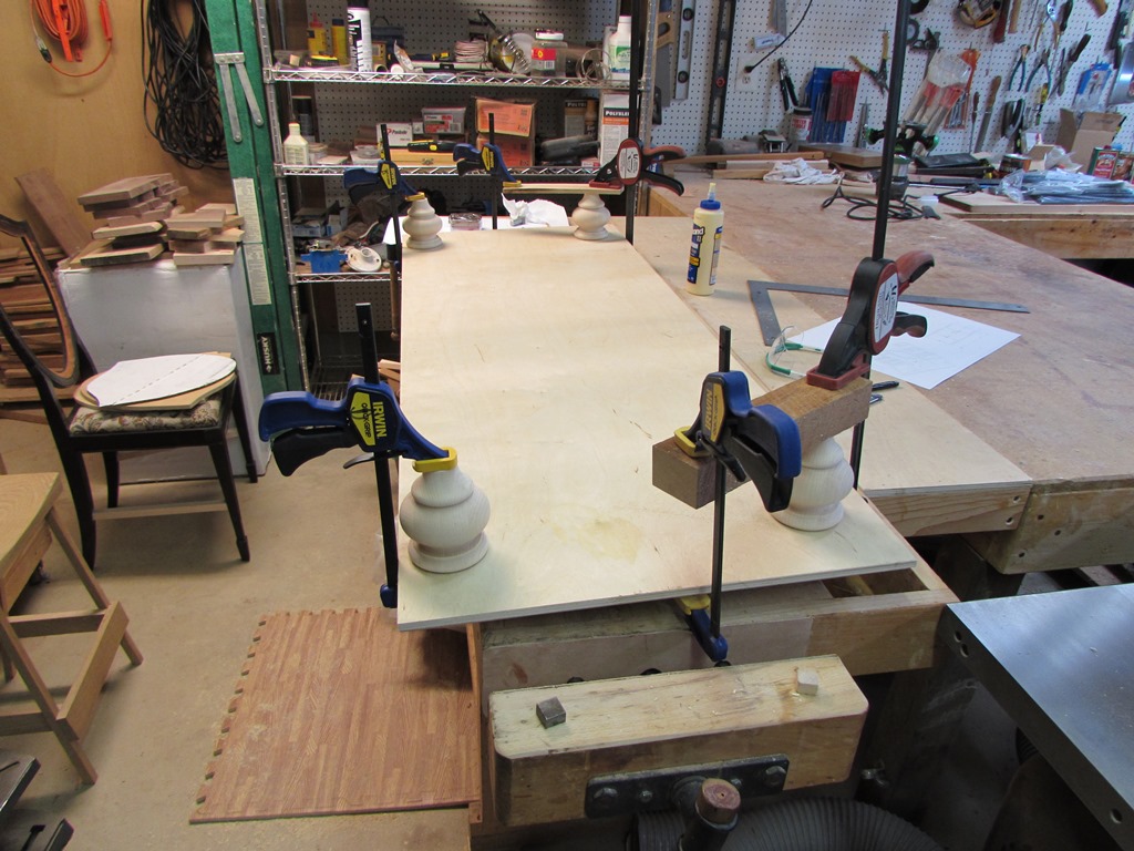
Before glueing up the sides, I wanted to install the feet. This will raise the cabinet up high enough to allow me to use clamps on the bottom when I attach the sides. I moved the feet around till I found an arrangement I thought would look good, then marked the center locations. I wound up coming in 4″ from the sides, and 2″ back from the front. Since you can’t really see the back legs, I brought them in 3″ from the back edge. That will help them to clear any base trim that may run behind the vanity.
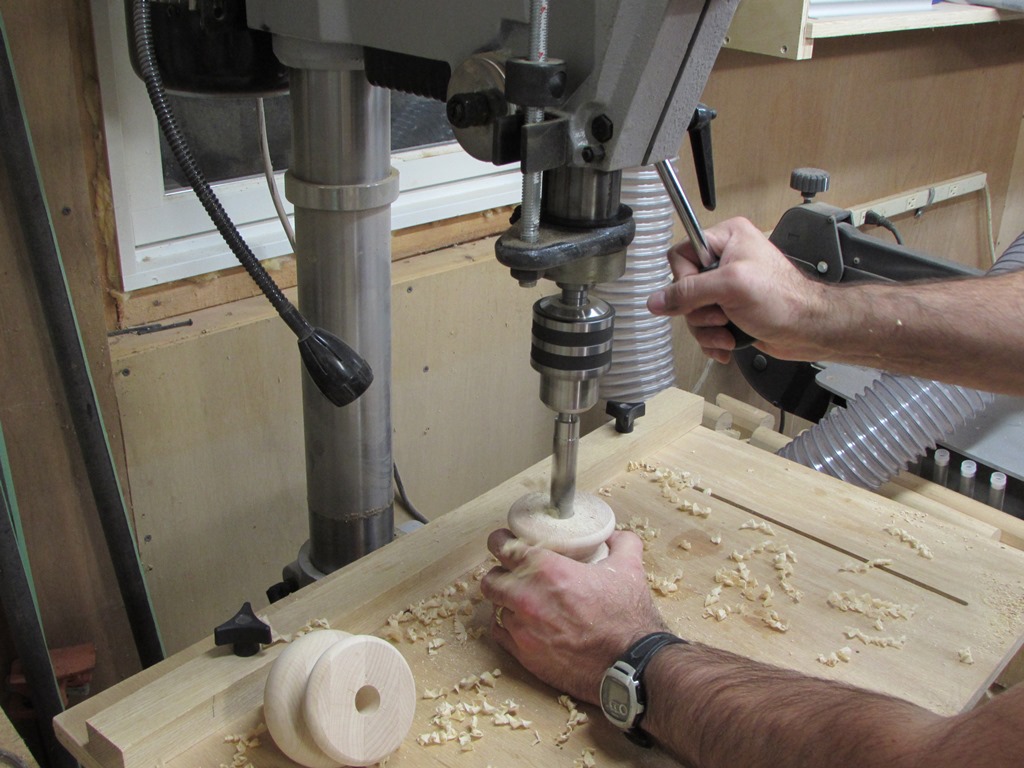
I held the feet firmly in place, while drilling them with a 3/4″ bit. They already had the centers marked from the manufacturing process, so they were easy to line up. I would probably recommend using some form of clamp in the future, since one of them did bind slightly and managed to burn a shiny ring into my hand, before I could let go… I drilled about 1″ deep into the feet, then drilled a 1/2″ deep hole into the plywood. In both cases, I used a pilot bit that created a flat-bottomed hole. I didn’t want to risk drilling through the plywood, and a flat bottom gives me more glue surface.

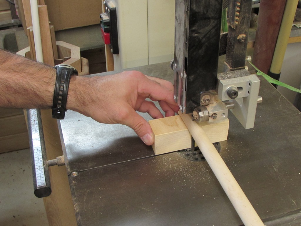
Next, I cut an old Vee block down to 1-1/2″ wide and cut four 1-1/2″ long dowels on the band saw off of a long piece of 3/4″ wood dowel, that I had.

After test fitting the feet, I applied glue and attached the feet to the base.

I clamped it up and let is set for about an hour.

While that was drying, I marked and cut out the notches in the two center walls.


When they were done, I grabbed a piece of poplar and cut and planed the rear stiffener.

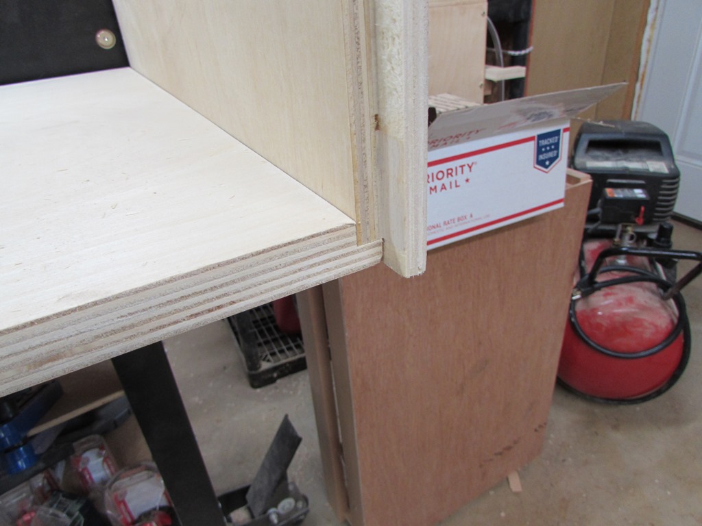
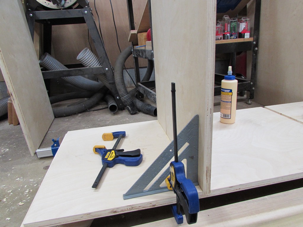
After the feet had dried sufficiently, I flipped the base over and set it on the floor. I applied glue to the center grooves and inserted the two center walls. I clamped a couple of speed squares in place to help me keep them perfectly square.

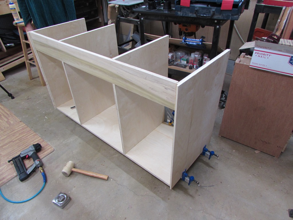
With the help of my wife, I glued and clamped the end walls in place, then added the rear stiffener. I only used a few brad nails to help hold the stiffener in place, until the glue dried.

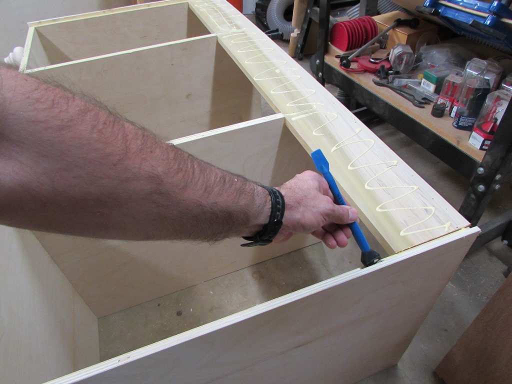
Next, we laid the carcass on the front face, and I applied glue to all the back edges.

I inserted the 1/2″ thick back panel, then clamped and nailed it in place.
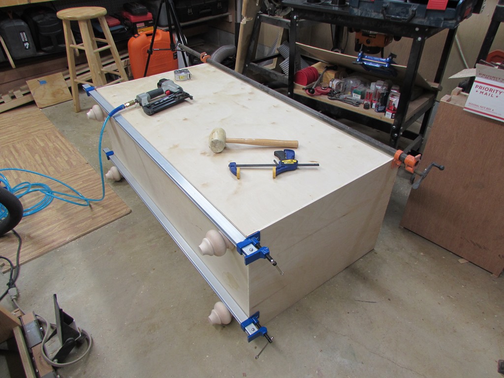
When dry it should be fairly rigid. The next step will be to create the face frame and attach it. Then everything will be locked tightly in place.
